Diaphragms are used to generate/transfer lateral loads, including wind and seismic loads.
Diaphragms does not generate any vertical loads. Please refer to Plates section for vertical loads.
Diaphragms behave like deep beams: they are subject to wind or seismic forces and apply reaction forces to supports (shear lines).
In LAVA, diaphragms have designated directions. Each diaphragm must be in either X direction (plan west-to-east, or left-to-right), or Y direction (plan north-to-south, or top-to-bottom). Diaphragm will only interact with the lateral elements in the same direction. For example, a diaphragm in X direction has nothing to do with the shear lines or shear walls in Y direction.
.png)
How to Model Diaphragms in LAVA
.png")
To model a diaphragm, first select the direction, X or Y in ‘Diaphragm Lat Dir’, and then click ‘Diaphragm’ on toolbar to start drawing diaphragms in the model space. There is also a keyboard shortcut ‘d’ to activate this drawing diaphragm command. Press the left button of mouse at the corner of an area of diaphragm and then release at the diagonal opposite corner of that area in the model space to model a diaphragm.
Navigating the Diaphragm Dialog
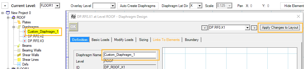
After drawing a diaphragm in the model space, you can double-click on the diaphragm to open the Diaphragm Design dialog. You can also double-click the Diaphragm Name in the navigation list on the left.
.png)
.png "image(583).png") : Click ‘OK’ button to save any edit/input and close the window.
: Click ‘OK’ button to save any edit/input and close the window.
.png "image(584).png") : Click on the top drop-down menu to quickly navigate all diaphragm members at this level. The left/right arrows allow you to also move to the previous/next diaphragm element.
: Click on the top drop-down menu to quickly navigate all diaphragm members at this level. The left/right arrows allow you to also move to the previous/next diaphragm element.
.png "image(585).png") : Click ‘Apply Changes to Layout’ button to save any edit/input.
: Click ‘Apply Changes to Layout’ button to save any edit/input.
Definition Tab
.png)
Diaphragm Name: Displays the diaphragm name. LAVA initially assign a name by default for diaphragm element. You can edit the name, press .png) , and it will be displayed on the navigation list on the left.
, and it will be displayed on the navigation list on the left.
Level: Displays the level of diaphragm. This information cannot be altered.
ID: Displays the internal ID of the diaphragm in program. This information cannot be altered.
Location X and Y: Displays the coordinates of the top-left corner of the diaphragm. You can edit these data to accurately place a diaphragm in the model space.
X-Width (Y-Length): Displays the dimension of the diaphragm in X direction (or Y direction).
Seismic Height Z: Displays the seismic height of the diaphragm. This information cannot be altered.
Support 0 Offset (or Support 1 Offset): You can assign left or top cantilever length at Support 0, and right or bottom cantilever length at Support 1. The default value is 0.
.png")
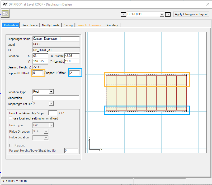
Location type: You can select Roof or Floor from drop-down menu to access load assemblies for roof or floor. The default value for diaphragms on roof level is Roof; the default value for diaphragms on floor level is Floor. This needs to be modified when you are modeling a roof deck, or a low roof.
Annotation: You can input descriptive notes for the record.
Diaphragm Lat Dir: Displays the directions of the diaphragm. This information cannot be altered.
Roof Load Assembly Slope: This option only shows up when ‘Roof’ is selected in Location Type. Roof dead load will be adjusted per the slope input here.
use local roof setting for wind loads: If the roof configuration is different from the default setting under ‘Profile’ tab, you can check this option.
Roof Type: If ‘use local roof setting for wind load’ is check, the drop-down menu is available to select from the following options: ‘Flat’, ‘Gable’, and ‘Monoslope’.
Ridge Direction: If ‘use local roof setting for wind load’ is check, and if Roof Type is selected as ‘Gable’ or ‘Monoslope’, the drop-down menu is available to select from the following options: ‘X dir’, and ‘Y dir’.
Ridge Location: If ‘use local roof setting for wind load’ is check, and if Roof Type is selected as ‘Gable’ or ‘Monoslope’, the drop-down menu is available to select from ‘N’ (north) and ‘S’ (south) for Ridge in X direction, or from ‘W’ (west) and ‘E’ (east) for Ridge in Y direction.
Parapet: If ‘use local roof setting for wind load’ is check, you can include the height of parapet in wind load calculation.
Basic Loads Tab
Gravity Tab
.png)
Gravity Load Assembly: The roof or floor load assembly associated with this diaphragm is listed under this tab. By default, ‘use default load assembly’ is checked, and the default load assembly is assigned to this diaphragm. You can uncheck ‘use default load assembly’ and select available assemblies that are previously defined in ‘Building Definition’ - ‘Load Assemblies’ tab. The available assemblies are consistent with the Location Type in Definition tab.
.png "image(592).png")
Snow Tab
Snow tab only show up if a diaphragm is designated as ‘Roof’ in Location Type under Definition tab. This page cannot be modified.
.png)
Please note: under ‘Design Procedure’ - ‘Snow’ tab, ‘Apply Snow Loads’ must be checked for this diaphragm to include snow loads.
.png "image(350).png")
Seismic Tab
Seismic tab displays the break-down of the total seismic weight (including roof or floor assembly weight, and wall weight in both directions), and gives you an opportunity to make adjustments of wall weight.
Please note, this tab will be updated after the entire model is finished and a full-scale analysis is done.
.png)
Apply Seismic Load Assembly: This option is checked by default. If you do not wish this diaphragm to generate seismic load, you can uncheck this option.
Manual Adjust Tributary Height: LAVA calculates wall weights with half of plate heights defined in Building Definition - Elevations tab. If this diaphragm has a higher or lower plate height, you can check this option, and Trib Height at Weight Adjustment section will become editable, so you are able to make adjustments to wall weight specifically to this diaphragm.
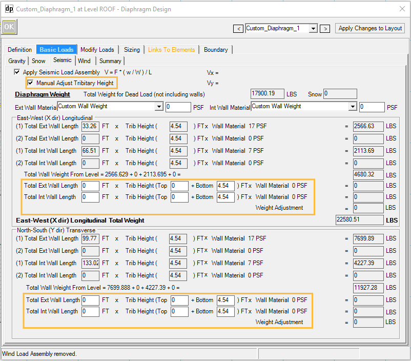
Diaphragm Weight: Displays the weight of the roof / floor assembly of this diaphragm. This information cannot be altered here.
Ext Wall Material: If wall weight adjustment is needed for this diaphragm, you can choose a pre-defined wall assembly, or enter a custom wall weight. Please note, Manual Adjust Tributary Height must be checked first before making adjustments.
.png)
Int Wall Material: If wall weight adjustment is needed for this diaphragm, you can choose a pre-defined wall assembly or enter a custom wall weight. Please note, Manual Adjust Tributary Height must be checked first before making adjustments.
.png)
East-West (X dir) Longitudinal: Displays the break-down of wall weight in X direction. We have previously input the total wall length of the structure in both directions under Building Definition - Wall tab. LAVA uses area ratio of this diaphragm to the totally combined diaphragms to calculate the proportion of the wall weight specific to this diaphragm in X direction. This information cannot be altered here, but you can make adjustments in Weight Adjustment section if Manual Adjust Tributary Height is checked.
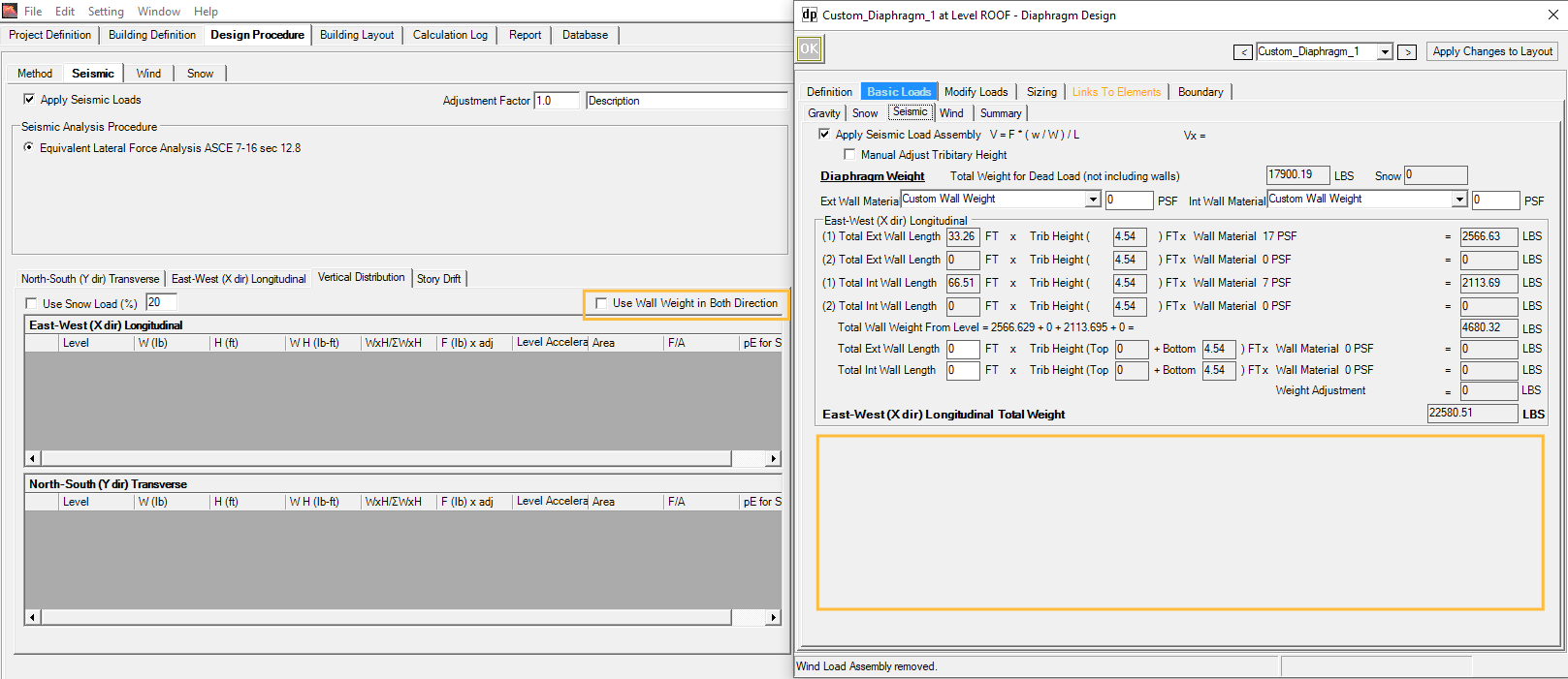
North-South (Y dir) Longitudinal: Displays the break-down of wall weight in Y direction. We have previously input the total wall length of the structure in both directions under Building Definition - Wall tab. LAVA uses area ratio of this diaphragm to the totally combined diaphragms to calculate the proportion of the wall weight specific to this diaphragm in Y direction. This information cannot be altered here, but you can make adjustments in Weight Adjustment section if Manual Adjust Tributary Height is checked. In this case, Y direction is the perpendicular to the direction of this diaphragm. If you unchecked Use Wall Weight in Both Direction under Design Procedure - Seismic - Vertical Distribution, the perpendicular wall weight will be discarded here.
Wind Tab
Wind tab displays the wind load in plf that this diaphragm is subject to and gives you an opportunity to make adjustments of wind forces on each side of the diaphragm specifically.
Please note, this tab will be updated after the entire model is finished and a full-scale analysis is done.
.png)
Apply Wind Load Assembly: This option is checked by default. If you do not wish this diaphragm to generate wind load, you can uncheck this option.
By default, LAVA will assume the building has uniform plate height and will automatically apply and/or block wind pressure of each side of each diaphragm according to the layout. If this is not true for your model, you can make adjustments on diaphragms with the following options.
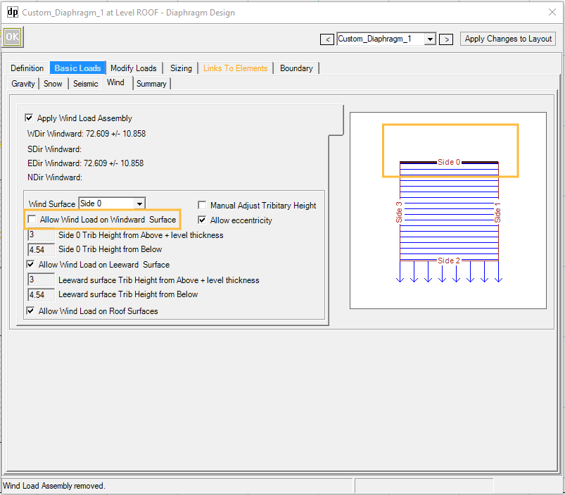
Wind Surface: You can customize the wind load generated by this diaphragm if the default setting is not applicable to this diaphragm. Select a side to start:
.png)
Once a side is picked from the drop-down menu, a diagram on the right is updated to help you visualized the revision. Select Side 0 for example.
Manual Adjust Tributary Height: LAVA calculates tributary heights with half of plate heights defined in Building Definition - Elevations tab. If this diaphragm has a higher or lower plate height, you can check this option, and tributary heights will become editable.
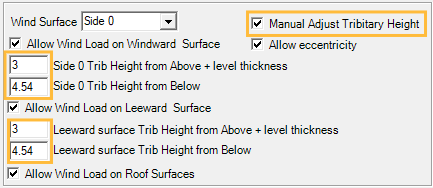
Allow eccentricity: This option is checked by default per ASCE 7 Chapter 27.4.6. If your structure meets the requirements of App.D1.1, you can uncheck this option accordingly.
Allow Wind Loads on Windward Surface: This is checked by default. If you want to disregard the wind pressure on the windward surface, you can uncheck this option, and the diagram will be updated for your reference.
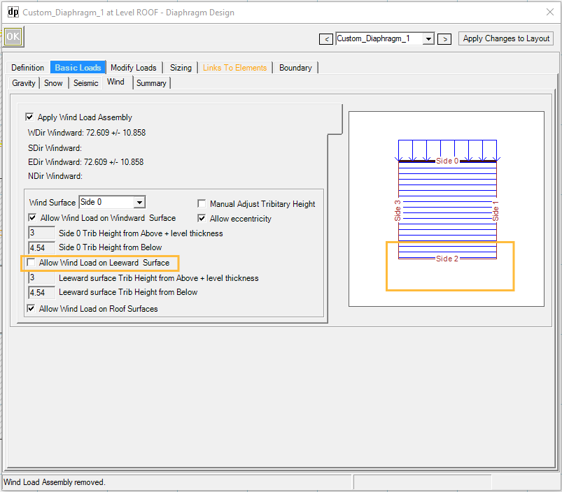
Allow Wind Loads on Leeward Surface: This is checked by default. If you want to disregard the wind pressure on the leeward surface, you can uncheck this option, and the diagram will be updated for your reference.
Summary Tab
Summary tab gives a graphical description of the loads on the diaphragm. Choose the item to display from the drop-down menu. This helps review and examine load conditions. Please note, this tab will be updated after the entire model is finished and a full-scale analysis is done.
.png) After selecting the load source (SW- Shear Wall), select the Load Category to show the loads (D- Dead Load, L- Live Load, Lr- Live Roof Load, Sn- Snow Load, W(+)- Wind Load Positive, W(-)- Wind Load Negative, E- Seismic Load). If the load category has no options and displays grey, that means there are no loads in that load category. Please note diaphragms only subject to lateral load, therefore the load source can only be other lateral structural elements such as Shear Walls.
After selecting the load source (SW- Shear Wall), select the Load Category to show the loads (D- Dead Load, L- Live Load, Lr- Live Roof Load, Sn- Snow Load, W(+)- Wind Load Positive, W(-)- Wind Load Negative, E- Seismic Load). If the load category has no options and displays grey, that means there are no loads in that load category. Please note diaphragms only subject to lateral load, therefore the load source can only be other lateral structural elements such as Shear Walls.
Select “All” to show all the sources of load together. Select “Reactions” to show the Diaphragm reactions.
Modify Loads Tab
In addition to automatic loading by LAVA, user can manually add loads under ‘Modify Loads’ tab, including point load (P), and distributed line load (w), and distributed area load (W). Simply use mouse to draw points, lines, or areas in the diagram on the right. The diagram is updated in time to reflect the loads. Use ‘Delete’ key on keyboard to remove loads.
.png)
Sizing Tab
Review the loading types and values in the background calculations. This is helpful to verify calculation for loading or results. The values displayed are all unfactored lateral loads in X or Y direction.
Typically, there are two or three blocks of data
The first block is the lateral loads generated by this diaphragm
The second block is the reaction of the shear walls from the level above. This block of data only shows up when there are shear walls directly placed on this diaphragm. Please note this will trigger Type 4 vertical irregularities per ASCE 7 Table 12.3-2
The third block is the reaction of this diaphragm
Links To Elements Tab
This tab displays the elements (Shear Lines) that are subject to the reactions of this diaphragm, including both automatic link by LAVA, and manual link by the user when applicable. This helps review the load path of this diaphragm.
.png)
Only Use Manual Links, Suggested Linking is Disabled: LAVA automatically traces the load paths basing on graphic representation in model space. They are listed in the summary list with ‘Auto’ marked on the left. If you wish to turn off the automatic tracing, and only relies on manual tracing, they can check this option. It is uncommon to check this option.
Auto Link X: If checked, LAVA automatically applies the diaphragm load to shear lines basing on graphic representation in model space. It is uncommon to uncheck this option.
Manual Link: Left reaction ‘Direction X0’, or right reaction ‘Direction X1’ of this diaphragm can be manually added to existing shear lines on the same level. Input the location measured from left/top end of the shear line to the reaction, and click .png) button on the right. You can choose the percentage of the reaction that are to be applied.
button on the right. You can choose the percentage of the reaction that are to be applied.
Lateral Link Margins: You can assign the margin in graphic accuracy for LAVA to capture the reactions of this diaphragm. Please see the screenshot in model space below:
.png)
If the margin of X0 is set to be 1’, the top reaction of this diaphragm will not be automatically captured by Shear Line A in the screenshot above, because 1.5’ is beyond the margin set by 1’; if the margin of X0 is set to be 2’, the top reaction of this diaphragm will be automatically captured by Shear Line A, since 1.5’ is within the margin set by 2’.
Lateral Links Margin Extend: You can assign the extend of margin limit set in Lateral Link Margins above, so you can control whether the reaction of diaphragm can be collected by a certain shear line or not.
Please see the following scenario: The extend of X0 margin is set ‘-1’ on the left side, and ‘5’ on the right side. That means shear lines beyond these extend will not collect any lateral loads from X0 reaction of this diaphragm.
.png)
.png)
Use limits: When unchecked, the extend of margin will be set as infinity, as shown in the screenshot below:
.png)
Boundary Tab
.png)
Allow Loads from Other Levels: You can choose if loads from elements on other levels are allowed to be applied to this diaphragm. It is uncommon to uncheck these items.
Isolate Reactions to Same Level: You can choose if reactions of this diaphragm are allowed to be applied to elements on the same level. These items can be checked if you are certain of the load path, and do not wish to accidentally over stress certain structural elements on the same level. It is uncommon to check these options.
Isolate Reactions to Other Levels: You can choose if reactions of this diaphragm are allowed to be applied to elements on the other levels. These items can be checked if you are certain of the load path, and do not wish to accidentally over stress certain structural elements on the lower levels. It is uncommon to check these options.