Plates are used to apply vertical (gravity) loads to beams, bearing walls, and shear walls.
Plates only generate vertical loads. Please refer to Diaphragm section for generating lateral loads.
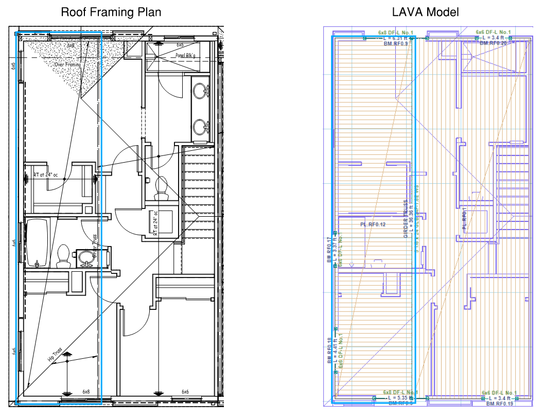
Plates behave like areas of framing. Please see the image below for a comparison between framing plan and LAVA model with plates modeled accordingly. The orientation and length of the thin orange lines of a plate represent the direction and span of the framing in that area.
.png")
How to Model Plates in LAVA
.png")
To model a plate, click ‘Plate’ on toolbar to start drawing plates in the model space. There is also a keyboard shortcut ‘a’ to activate this drawing plate command. Click at the corner of an area of framing and at the diagonal opposite corner of that area in the model space to define a plate. LAVA automatically assign the framing span in the short direction.
Navigating the Plate Dialog
After drawing a plate in the model space, you can double-click on the plate to open the Plate Design dialog. You can also double-click the Plate Name in the navigation list on the left.
.png "image(302).png")
.png "image(303).png") : Click ‘OK’ button to save any edit/input and close the window.
: Click ‘OK’ button to save any edit/input and close the window.
.png "image(304).png")
: Click on the top drop-down menu to quickly navigate all plate elements at this level. The left/right arrows allow you to also move to the previous/next beam element.
.png "image(305).png") : Click ‘Apply Changes to Layout’ button to save any edit/input.
: Click ‘Apply Changes to Layout’ button to save any edit/input.
Plate Definition Tab
.png "image(301).png")
Plate Name: Displays the plate name. LAVA initially assign a name by default for plate element. You can edit the name, and it will be displayed on the navigation list on the left.
.png")
Level: Displays the level of the plate. This information cannot be altered.
ID: Displays the internal ID of the plate in program. This information cannot be altered.
Location X and Y: Displays the coordinates of the top-left corner of the plate. You can edit these data to accurately place a plate in the model space.
X-Width (Y-Length): Displays the dimension of the plate in X direction (or Y direction).
Seismic Height Z: Displays the seismic height of the plate. This information cannot be altered.
Support 0 Offset (or Support 1 Offset): You can assign left or top cantilever length at Support 0, and right or bottom cantilever length at Support 1. The default value is 0.
.png")
Span: You can select the direction of the framing. The default option is ‘Short Dir’, spanning in short direction.
Location type: You can select Roof or Floor from drop-down menu to access load assemblies for roof or floor. The default value for plates on roof level is Roof; the default value for plates on floor level is Floor. This needs to be modified when you are modeling a roof deck, or a low roof.
Annotation: You can input descriptive notes for the record.
Roof Load Assembly Slope: This option only shows up when ‘Roof’ is selected in Location Type. Roof dead load will be adjusted per the slope input here.
Plate Basic Loads Tab
Gravity Tab
.png "image(308).png")
Gravity Load Assembly: The roof or floor load assembly associated with this plate is listed under this tab. By default, ‘use default load assembly’ is checked, and the default load assembly is assigned to this plate. You can uncheck ‘use default load assembly’ and select available assemblies that are previously defined in ‘Building Definition’ - ‘ Load Assemblies’ tab. The available assemblies are consistent with the Location Type in Definition tab.
.png "image(309).png")
Snow Tab
Snow tab only show up if a plate is designated as ‘Roof’ in Location Type under Definition tab. This page cannot be modified.
.png "image(349).png")
Please note: under ‘Design Procedure’ - ‘Snow’ tab, ‘Apply Snow Loads’ must be checked for this plate to include snow loads.
.png "image(350).png")
Summary Tab
.png "image(352).png")
This screen gives a graphical description of the loads on the plate. Choose the item to display from the drop-down menu. This helps review and examine load conditions.
After selecting the load source (BM- Beam, PL- Plate, BW- Bearing Wall) select the Load Category to show the loads (D- Dead Load, L- Live Load, Lr- Live Roof Load, Sn- Snow Load, W(+)- Wind Load Positive, W(-)- Wind Load Negative, E- Seismic Load). If the load category has no options and displays grey, that means there are no loads in that load category. Please note plate is only subject to vertical load, therefore the load source can only be other vertical structural elements such as Beam, Plate, and Bearing Walls.
Select “All” to show all the sources of load together. Select “Reactions” to show the Plate reactions.
Plate Modify Loads Tab
In addition to automatic loading by LAVA, user can manually add loads under ‘Modify Loads’ tab, including point load (P), and distributed line load (w), and distributed area load (W). Simply use mouse to draw points, lines, or areas in the diagram on the right. The diagram is updated in time to reflect the loads. Use ‘Delete’ key on keyboard to remove loads.
Please note: the loads listed under ‘Modify Loads’ are in addition to the automatic loading by LAVA. They will not replace any automatic loading by LAVA.
.png "image(353).png")
Plate Sizing Tab
Review the loading types and values in the background calculations. This is helpful to verify calculation for loading or results. The values in the summary are all unfactored. ‘Z’ represents vertical forces.
.png "image(355).png")
Typically, there are two blocks of data.
The first block is the loading applied to the plate.
The second block is the reaction of the plate.
Plate Links To Elements Tab
This displays the elements that are subject to the reactions of the plate, including both automatic link by LAVA, and manual link by the user when applicable. This helps review the load path of the plate.
.png "image(356).png")
Only Use Manual Links, Suggested Linking is Disabled: LAVA automatically traces the load paths basing on graphic representation in model space. They are listed in the summary list with ‘Auto’ marked on the left. If you wish to turn off the automatic tracing, and only relies on manual tracing, they can check this option. It is uncommon to check this option.
Auto Link Z: If checked, LAVA automatically applies the plate load to vertical elements (Plate, Beam, and Bearing Walls) basing on graphic representation in model space. It is uncommon to uncheck this option.
Manual Link: Left reaction ‘Direction Z0’, or right reaction ‘Direction Z1’ of this plate can be manually added to existing structural elements on the same level. Input the location measured from left/top end of the element subject to the reaction, and click .png "image(358).png") button on the right. You can choose the percentage of the reaction that are to be applied.
button on the right. You can choose the percentage of the reaction that are to be applied.
.png "image(357).png")
Vertical Link Margins: You can assign the margin in graphic accuracy for LAVA to capture the reactions of this plate. Please see the screenshot in model space below:
.png "image(359).png")
If the margin of Z1 is set to be 0.01’, the right reaction of Plate PL.FL2.2 will not be automatically included into the calculation of BM.FL2.1 by LAVA, because 5” is beyond the limit of 0.01’; if the margin if Z1 is set to be 0.5’, the right reaction of Plate PL.FL2.2 will be automatically included into the calculation of BM.FL2.1 by LAVA, because 5” is within the limit of 0.01’:
.png "image(360).png")
Plate Boundary Tab
.png "image(362).png")
Allow Loads from Other Levels: You can choose if loads from elements on other levels are allowed to be applied to this plate. It is uncommon to uncheck these items.
Isolate Reactions to Same Level: You can choose if reactions of this plate are allowed to be applied to elements on the same level. These items can be checked if you are certain of the load path, and do not wish to accidentally over stress certain structural elements on the same level. By default, LAVA will uncheck all these elements except for the uplifting reactions to beams as shown in screenshot above. It is uncommon to make modifications to these options.
Isolate Reactions to Other Levels: You can choose if reactions of this plate are allowed to be applied to elements on the other levels. These items can be checked if you are certain of the load path, and do not wish to accidentally over stress certain structural elements on the lower levels. By default, LAVA will uncheck all these elements except for the uplifting reactions to beams as shown in screenshot above. It is uncommon to make modifications to these options.
use this plate to create dp in x dir (or use this plate to create dp in y dir): These options are checked by default. LAVA can generate diaphragms in X and Y directions basing on the geometry of plates. Click ‘Auto Diaphragm’ above model space:
.png")
Please note: this operation will remove all existing diaphragms on all levels.
.png "image(363).png") LAVA will automatically divide plates to add smaller diaphragms at locations of shear walls. Please see the plate below. If shear walls are modeled at the interior location of the plate:
LAVA will automatically divide plates to add smaller diaphragms at locations of shear walls. Please see the plate below. If shear walls are modeled at the interior location of the plate:
.png")
LAVA will automatically generate a smaller diaphragm on the right side of these shear walls:
.png "image(366).png")
LAVA will not automatically generate cantilever diaphragms.