Shear Wall Deflection
Shear Walls are designed and sized for capacity and also for deflection.
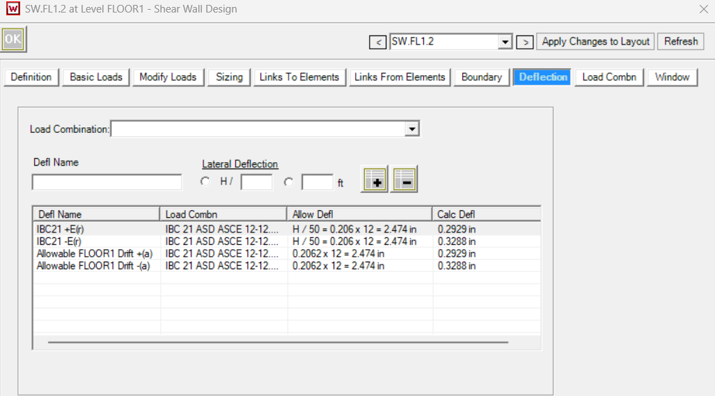
You can review the deflection calculated per shear wall in the Shear Wall dialog, Deflection tab.
How to Change the Deflection Criteria for Shear Walls
The deflection criteria can be adjusted for the entire model.
The Database- Deflection tab displays all the deflection load combinations and criteria.
To change the deflection follow these steps:
Step 1: Click on the Load Combination to be changed.
Step 2: Adjust the Lateral Deflection criteria.
Step 3: Click “Edit Defl” to save these values to the model file.
I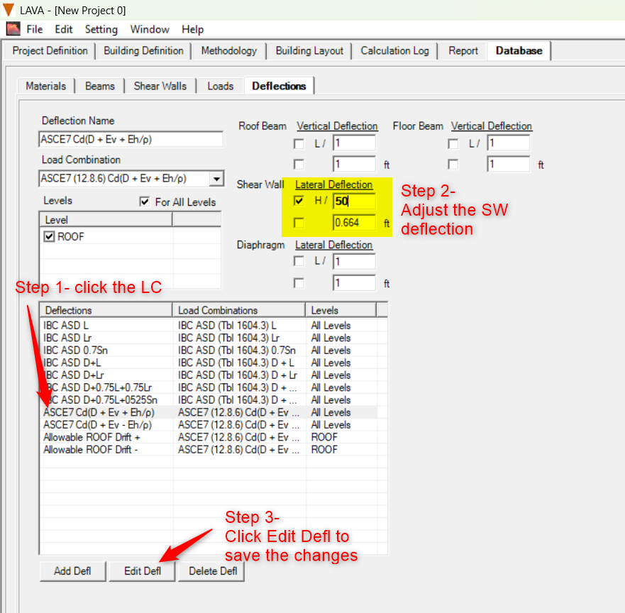
Hold-Down and Tie-Down Shear Wall Drift
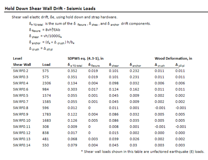
LAVA reports shear wall drift for seismic loading using the unfactored earthquake load, (E). Seismic drift is evaluated using the wall’s elastic deflection and is later amplified by the applicable seismic deflection amplification factor, (C_d), for the code drift check.
The reported shear wall load in this table is the unfactored seismic shear assigned to the wall.
Three-Part Deflection Equation
LAVA calculates the elastic shear wall deflection using the simplified three-term equation from SDPWS:
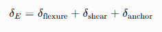
The three terms represent:
Chord flexure or axial deformation
Sheathing and fastener shear deformation
Hold-down or tie-down anchorage deformation
Hold-Down Shear Walls
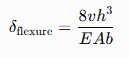
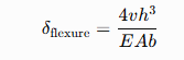
For shear walls using conventional hold-down hardware, the flexure component is calculated as:
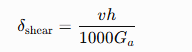
The shear deformation component is:
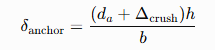
The anchorage component is:
Therefore, the total elastic wall deflection is:

Tie-Down Shear Walls
For walls using a continuous tie-down system, LAVA uses a coefficient of 4 instead of 8 in the flexure term:
Why does LAVA use 4 instead of 8 for tie-down systems?
The SDPWS equation was developed for conventional shear walls with discrete hold-downs at each end of the wall. Continuous tie-down systems behave differently because the continuous rod restrains the chord over the full height of the structure rather than only at the wall segment. This reduces the chord flexure component of wall deflection. To account for this difference, LAVA uses a coefficient of 4 in the flexure term for tie-down systems. The deformation of the tie-down hardware, rods, bearing plates, couplers, and wood bearing is then calculated separately and included in the anchorage term, providing a more representative prediction of the total wall drift.
The coefficient is reduced because the continuous tie-down system develops tension and compression through the full-height restraint system differently than a conventional wall with discrete hold-downs at the wall ends.
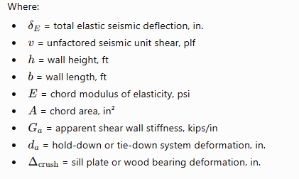
Variable Definitions
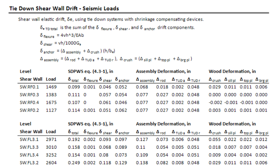
Viewing Drift Results in the Calculation Log
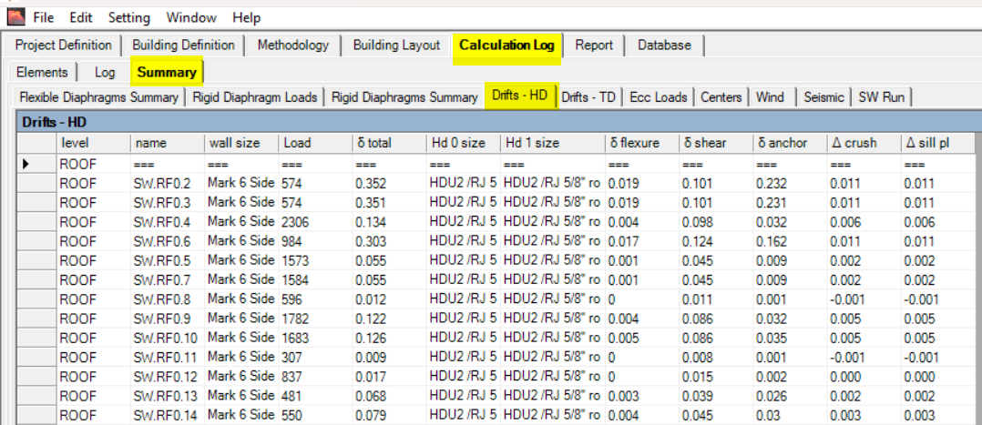
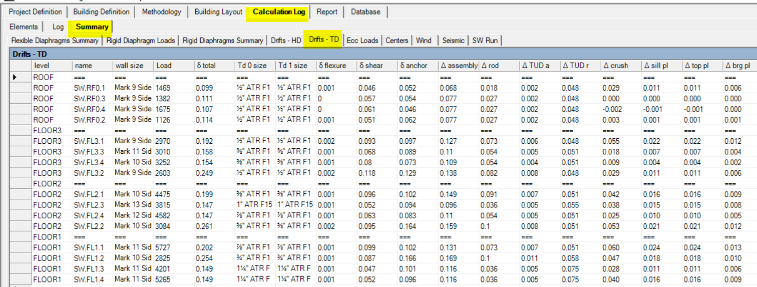
This same drift information is also available in the Calculation Log under the Summary tab. Enable the applicable drift summary option, then analyze the model to populate the table. The summary displays the total deflection and each individual deflection component for the walls in the model. It also provides a convenient way to select, copy, and paste the results directly from LAVA into a spreadsheet for further review or documentation.