Flexible Diaphragm - Tributary Area
LAVA distributes the lateral loads from the diaphragm to the shear lines based on the tributary area. The shear lines then distribute lateral loads to the walls within the shear lines in proportion to their stiffness or adjusted strengths.
The flexible approach distributes Diaphragm lateral loads to Shear Lines based on a series of one or more simply supported beams spanning between Shear Lines. Shear Line loads from above a shear line are treated as passing directly to the shear line below with no consideration given to diaphragm action. The collector line itself is assumed to be rigid.
Rigid Diaphragm - Rigid Stiffness
Solutions utilizing the rigid diaphragm approach will distribute loads to Shear Walls (not to the Shear Lines) based on the stiffnesses of each individual wall and its orientation relative to the centers of mass, rigidity under wind load and rigidity under seismic load. Centers of rigidity differ between wind seismic because the stiffness of the shear walls themselves are not linear with respect to loading. Shear Wall stiffnesses are calculated based on unfactored loading, W and E. Loads from above are resisted by diaphragm action as a whole (not by the user defined Diaphragms) and in turn the diaphragm transfers these forces to Shear Walls below or the building’s base. Because of this load path, the forces resisted by Shear Walls above the diaphragm may be greater than the amounts in turn imposed on Shear Walls directly below. Shear Walls along a Shear Line may not have exactly the same stiffnesses. ASCE7 -22 12.8.4.2 Accidental Torsion requires the assumed torsional displacement equal 5% of the building’s dimension at the level perpendicular to the direction of the applied forces for many building configurations.
LAVA performs rigid diaphragm analysis using a trial-and-error process. That is by far the most rigorous method used. The steps involved are as followings:
Run a flexible analysis to serve as the first trial
Compute shear wall rigidities based on flexible results
Redistribute lateral force based on shear wall stiffness
Size Shear walls using new forces from rigid analysis
Redistribute lateral force based on new shear wall sizes
Check if shear wall sizes work under new loads from previous step. If it works- stop. Otherwise, resize and redistribute until it passes.
Output the final results
Step 1: Flexible Analysis
This is further described in the Flexible diaphragm section of this article.
Step 2: Compute Shear Wall Rigidities
In LAVA, shear wall rigidity k is calculated using the basic stiffness equation:
.png "image(404).png")
The shear wall deflection D is calculated using the simplified 3-term equation that suggested at the “2005 Special Design Provisions for Wind and Seismic (SDPWS)” by the American Forest and Paper Association (AF&PA).
.png "image(405).png")
v = strength level shear stress (plf)
h = shear wall height (ft)
E = modulus of elasticity of the chord (psi)
b = width of shear wall (ft)
A = cross-section area of chord (in2)
Ga =Apparent Shear Stiffness (kips/in)
da = Total vertical elongation of wall anchorages system, including fastener slip, hold-down deformation, strap elongation, rod elongation between floor-to-floor hold downs, and plate crushing.
It should be pointed that the small differences in computed shear wall deflections from using the 4-term equation versus 3-term equation will impact shear wall rigidities and load distribution.
Step 3: Redistribute Lateral Forces based on Rigid Analysis
In this step, the shear forces are redistributed to the shear walls supporting each level using the rigid diaphragm assumption. Forces to shear walls are the sum of the forces due to direct shear proportional to the shear wall stiffness (V rigid) and eccentric forces due to the torsional moment (V eccentric).
a) Direct Shear Force
Direct shear force is determined using this calculation:
.png "image(406).png")
b) Torsional Shear Force
For rigid diaphragm, the distribution of lateral forces at each level considers both the effect of the inherent torsional moment (Mt) and accidental torsion (Mta). The inherent torsional moment results from eccentricity between the locations of the center of mass and the center of rigidity. The accidental torsion comes from assumed displacement of the center of mass each way from its actual location. The code (ASCE 7-22 12.8.4.2) requires the assumed displacement equals to 5% of the building dimension at the level perpendicular to the direction of the applied forces. It should be noted that this moment is resisted by the shear walls on the four sides of the building. The torsional force is determined from:
.png "image(407).png")
where e'= eccentricity including actual eccentricity and accidental eccentricity; d = distance from shear wall to the center of rigidity.
Step 4: Sizing Shear Walls with New Forces from Rigid Analysis
A wall size is selected and the capacity is checked based on the shear applied versus the wall capacity, the tie-down selected and boundary post requirements. Then the deflection calculated to ensure that it is within the drift requirements.
Step 1: Wall needs to meet the capacity requirement
Step 2: Check that deflection meets the drift limits.
Step 5: Redistribute Lateral Forces Based on Shear Wall Stiffness
All the walls are now sized, and the stiffness is recalculated for each wall. Step 3 is repeated to ensure the loads are accurately placed on the walls based on their calculated stiffness.
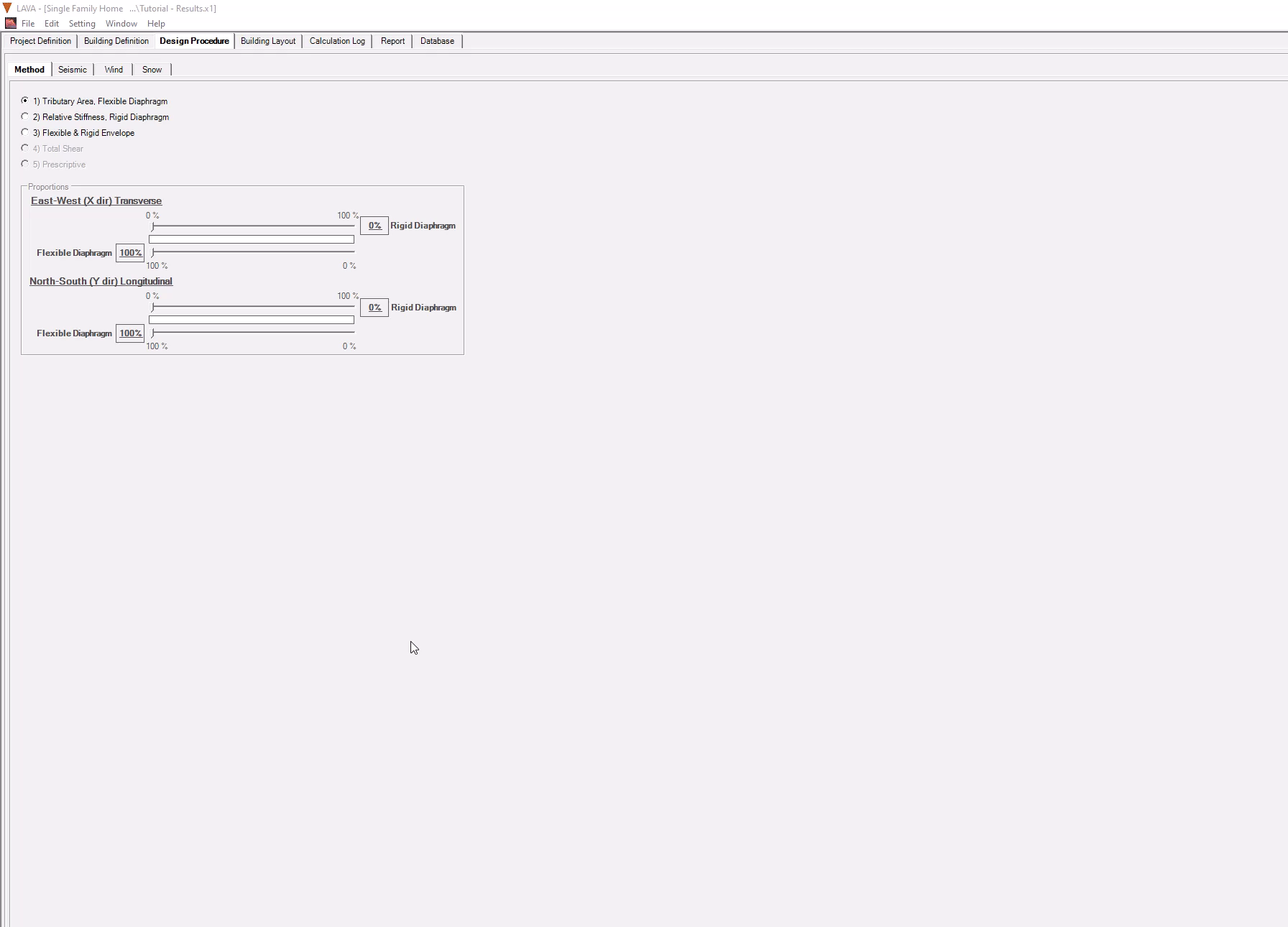
Flexible & Rigid Envelope
Envelope Solutions
These dials allow you to control the percentage of each type of analysis.
Worst case envelope would be to have 100% of Rigid diaphragm shear force and 100% of Flexible diaphragm shear force applied at the same time. This would be commonly used approach.
This screen allows you to dial in how much you would like to use
.png "image(1).png")
It is suggested you dial Flexible percentage first (Rigid percentage will move accordingly to make up to 100%), and then dial Rigid percentage to desired amount. You can have different setting for X and Y directions. In the recording below, the combination in X direction is 90% Flexible + 90% Rigid; and the combination in Y direction is 100% Flexible + 100% Rigid.