Beams are used to support vertical (gravity) loads.
In LAVA, vertical loads can be added to beams automatically if plate elements are modeled. Refer to Plates section for additional information.
LAVA can calculate simply supported beams, and with cantilever condition on either end. Beams are assumed to be pin-pin end conditions.
LAVA will perform live load reduction automatically per ASCE 7-16 Chapter 4.7 when applicable.
How to Model Beams in LAVA
.png")
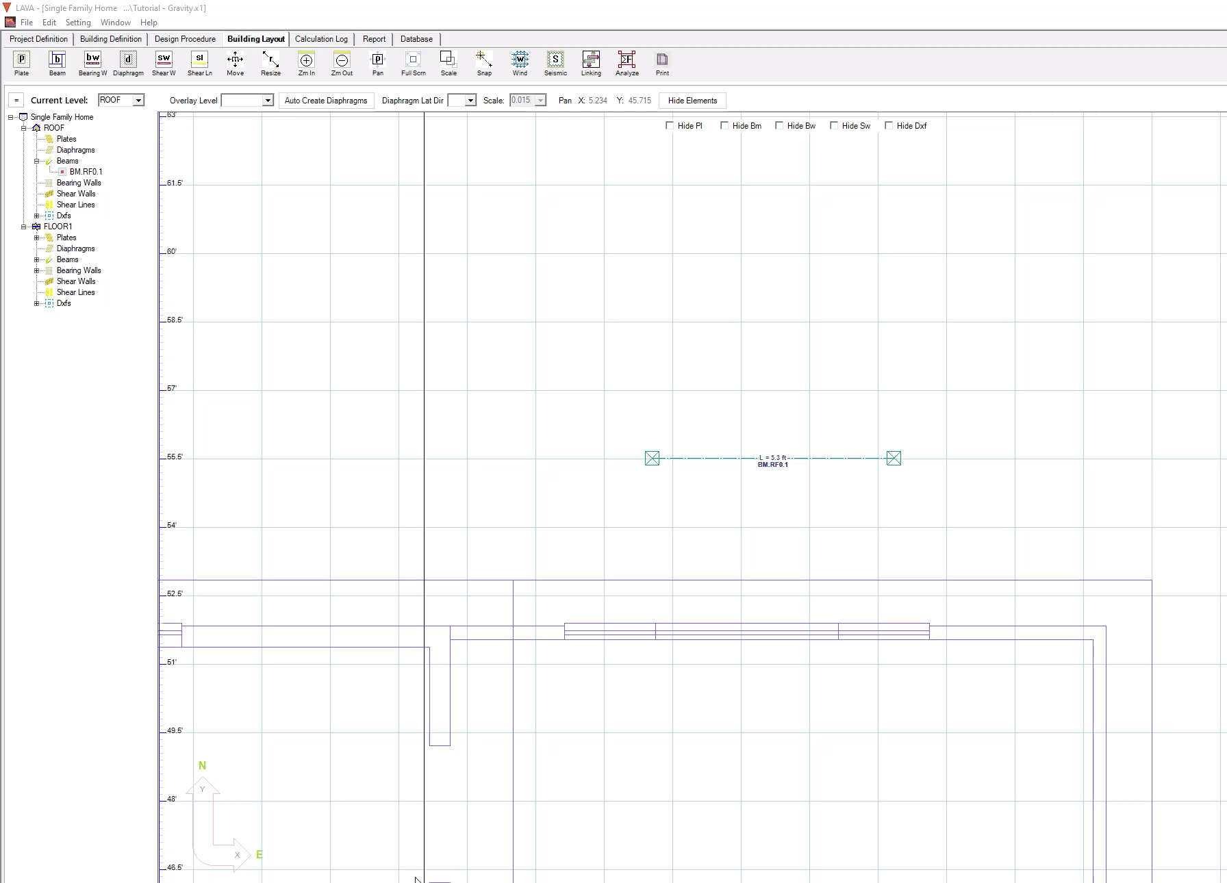
To model a beam, click ‘Beam’ on toolbar to start drawing beams in the model space. There is also a keyboard shortcut ‘b’ to activate this drawing beam command. Click at the starting and at the end point in the model space to define the length of the beam. Beams are automatically supported at each end after they are drawn.
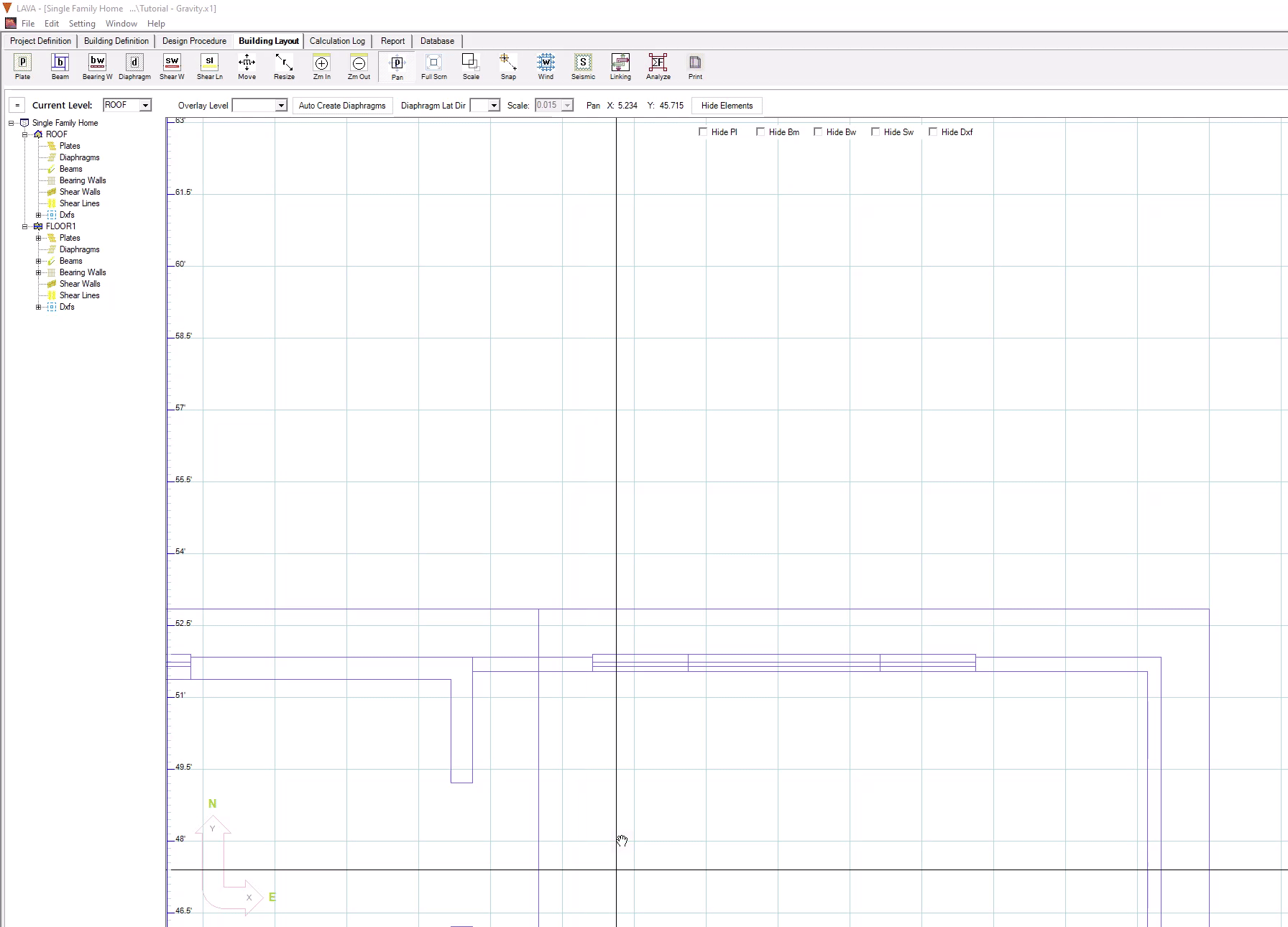
Beam Length is measured from start point (center of start supporting post) to end point (center of end supporting post).
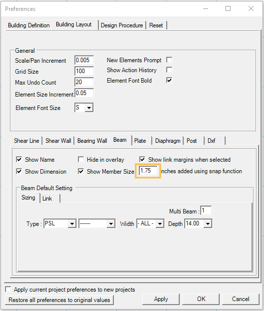
Pressing ‘Shift’ key on keyboard will activate the SNAP function. If beam is drawn with SNAP function, LAVA will automatically offset the center of posts to a predefined distance, so the clear span between posts will be consistent with the clear span of the background.
The default value of the offset is 1.75”, which is half of the width of 4x posts. You can change this value at Setting → Preferences → Building Layout → Beam tab.
See the Supports Section in the Sizing tab for further details.
Navigating the Beam Dialog
After drawing a beam in the model space, you can double-click on the beam to open the Beam Design dialog. You can also double-click the Beam Name in the navigation list on the left.
.png "image(239).png")
.png "image(200).png") : Click ‘OK’ button to save any edit/input and close the window.
: Click ‘OK’ button to save any edit/input and close the window.
.png "image(236).png") : Click on the top dropdown to quickly navigate all beam elements at this level. The left/right arrows allow you to also move to the previous/next beam element.
: Click on the top dropdown to quickly navigate all beam elements at this level. The left/right arrows allow you to also move to the previous/next beam element.
.png "image(238).png") : Click ‘Apply Changes to Layout’ button to save any edit/input without closing the window.
: Click ‘Apply Changes to Layout’ button to save any edit/input without closing the window.
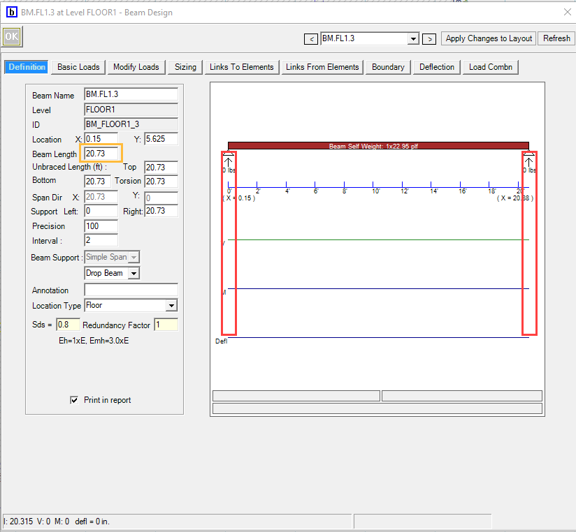
Beam Definition Tab
.png "image(240).png")
Beam Name: Displays the beam name. LAVA initially assign a name by default for beam element. You can edit the name, and it will be displayed on the navigation list on the left, and on the calculation report.
.png")
.png")
Level: Displays the level of the beam. This information cannot be altered.
ID: Displays the internal ID of the beam in program. This will not be displayed in calculation report. This information cannot be altered.
Location: Displays the coordinates of the left/top end of the beam. You can edit these data to accurately place a beam in the model space.
Beam Length: Displays the length of the beam.
Unbraced Length, Top: Displays the length between points that are braced against lateral displacement of top edge of wood beam, or top flange of steel beam. The default value is the length of beam, which yields conservative results. You can edit basing on true condition.
Unbraced Length, Bottom: Displays the length between points that are braced against lateral displacement of bottom edge of wood beam, or bottom flange of steel beam. The default value is the length of beam, which yields conservative results. You can edit basing on true condition.
Precision: During analysis, the beam is broken up into segments and each segment is a data point to calculate the moment/shear. This number represents the number of segments the beam is broken up into.
Span Dir, X (or Y): Displays the span of this beam in either direction. This information is consistent with beam length, and it cannot be altered. You must edit Beam Length to make adjustments.
Support, Left (or Right): Displays the location of support measuring from the left end of the beam. You can edit the location of support to model cantilever conditions.
Cantilever Example: support locations are adjusted to make up 2’ cantilever on the left end (marked with yellow rectangle), and 1’ cantilever on the right end (marked with blue rectangle).
.png")
Interval: Displays the scale in the diagram on the right. See below for comparison with intervals being 1 and 2.
.png "image(250).png")
Beam Support: Displays the type of the beam. This is for display purposes only- it will not affect the calculations.
This will be displayed in calculation report.
.png "image(253).png")
.png "image(256).png")
Annotation: You can input descriptive notes that will be displayed on the calculation report.
.png")
.png")
Location Type: You can select roof or floor from drop-down menu. If the beam is located on the Roof it will receive Roof loads, otherwise it will get Floor type loading.
Sds: Displays Sds that was input in ‘Project Definition’ - ‘Criteria’ - ‘Seismic’ tab. This will be used in special seismic load combinations.
Redundancy Factor: Displays redundance factor that was determined in ‘Project Definition’ - ‘Criteria’ - ‘Seismic’ tab. Note this can be turned off in the Design Procedure- Seismic tab- “Use Redundancy Factor”.
Beam Basic Loads Tab
This screen gives a graphical description of the loads on the beam.
.png "image(262).png")
Summary: Displays all the loads applying to this beam. Choose the item to display graphically. This helps review and examine load conditions.
After selecting the load source (SW- Shear Wall, BM- Beam, PL- Plate, BW- Bearing Wall) select the Load Category to show the loads (D- Dead Load, L- Live Load, Lr- Live Roof Load, Sn- Snow Load, W(+)- Wind Load Positive, W(-)- Wind Load Negative, E- Seismic Load). If the load category has no options and displays grey, that means there are no loads in that load category.
Select “All” to show all the sources of load together. Select “Reactions” to show the Beam reactions.
.png "image(263).png")
Beam Modify Loads Tab
In addition to automatic loading by LAVA, user can manually add loads under ‘Modify Loads’ tab, including point load (P), and distributed load (w). Use ‘From’ and ‘To’ .png "image(265).png") to designate location of loads. Click ‘OK’
to designate location of loads. Click ‘OK’ .png "image(266).png") after adding/editing each load. Use ‘Delete’ key on keyboard to remove loads.
after adding/editing each load. Use ‘Delete’ key on keyboard to remove loads.
.png "image(264).png")
Beam Sizing Tab
The Sizing tab is used to design the Beam Sizes, Supports.
.png)
.png "image(268).png") : By clicking this button, the beam will be calculated with current loading and configurations without running full model analyze.
: By clicking this button, the beam will be calculated with current loading and configurations without running full model analyze.
Load Combn: Choose ‘-Compare All-’ to calculate this beam with all available load combinations, and the worst-case scenario will be displayed at sub window on the right. You can also select a specific load combination from the dropdown menu to calculate this beam, and the calculation report will only display the result of this specific load combination for this beam.
Beam Sizes Tab
Up to three options can be designed and saved for each beam element. The selected option will be part of the calculation report.
.png)
Beam Types: The drop-down menu displays the available beam species and grades.
.png "image(271).png")
Width, Depth: The drop-down menu allow you to filter the candidate size pool of this beam.
.png "image(272).png")
AAF: Allowable Adjustment Factor allows you to increase or decrease the design limit (demand/capacity ratio) of the beam.
Multi Beam: Default value is 1. You can edit to design composite beam with multiple members sistering side-by-side. Please note, LAVA will calculate stability factor CL with the individual dimension of each beam. For example, for (3) 2×10, CL will be calculated based on 1.5”x9.25” dimension, which is one individual 2×10 beam.
Combined Width for CL: If checked, LAVA will calculate stability factor CL with combined dimension of multi-beam. For example, for (3) 2×10, CL will be calculated based on 4.5”x9.25” dimension, which is combined dimension of (3) 2×10 beam. To use this option, the multi-beam should be properly detailed to justify this approach.
Cr=1.15: When checked, the multi beam will be designed with applicable repetitive factor.
Beam Size: The drop-down menu lists all available sizes for the beam with selected specie, grade, width or depth. If ‘-All'-’ is selected, LAVA will automatically select the optimal size for this beam.
Recommendations: Displays the design beam size. If ‘-All-’ is selected at ‘Beam Size’, the optimal size selected by LAVA for this beam will be displayed.
copy this beam size to all existing beams: When checked, this beam size will be applied to all beams on this level, or to all beams on all levels.
.png "image(273).png")
Calculation Result is displayed at the sub window on the right, including applicable design factors, live load reduction, and shear, bending, and deflection results with pertinent load combinations.
Beam Load Summary
Review the loading types and values in the background calculations. This is helpful to verify calculation for loading or results. The values in the summary are all unfactored. ‘Z’ represents vertical forces.
.png "image(276).png")
There are two blocks of data.
The first block is the loading applied to the beam.
The second block is the reaction of the beam.
Support Tab
Support 0 (or Support 1): LAVA will calculate support post at left/top end of the beam as ‘Support 0’, and right/bottom end of the beam as ‘Support 1’. You can opt out by selecting ‘N/A’ in the drop-down menu.
.png "image(274).png")
Multi Post: LAVA can calculate multi-studs or multi-posts, up to (4) members. The default value is 1.
Effective unbraced length: LAVA will calculate compression capacity of post basing on the input effective unbraced length. The default value is the plate height defined in ‘Building Definition’ - ‘Elevations’ tab.
Unbraced Axis: LAVA will calculate compression capacity of post basing on the selected unbraced axis. The options are: Depth (unbraced parallel to beam span), Width (unbraced perpendicular to beam span), and Fully Braced (braced in both axes).
Post Type: You can select the species, grade, depth, and AAF (Allowable adjustment factor) of post. Lumber for studs/posts up to 4x, and Timber for posts larger than 4x.
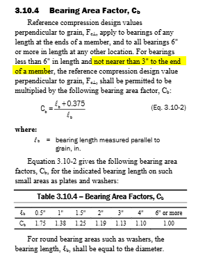
Wall Plate Bearing: LAVA will calculate sill plate bearing area factor Cb per NDS 3.10.4 basing on the selected option (Within 3 in. to end, or More than 3 in. from end). You can also tell LAVA Do not check.
.png")
The NDS uses the same language in the description of this section.
Post Sizes: The drop-down menu lists the available sizes for calculation. If user chooses ‘-All-’, LAVA will automatically assign the recommended size.
Size Recommendation: Displays the post size selected by LAVA per the loading requirement. If the size assigned does not work, or none of the available size works, it will display ‘Failed’. You must select a different post specie or grade.
Calculation Result is displayed at the sub window right below Support 0 (or Support 1), including applicable design factors, compression check, and sill plate bearing check with pertinent load combinations.
Beam Adjustment Factors
The Adjustment factors are defined for the entire model in the ‘Building Definition’ - ‘Adjustment Factors’ tab. The Adjustment factors can be adjusted or excluded for individual beam on this tab. Click on the factor from the dropdown list and the database of factors will show. These can be altered here for this beam only. Or uncheck the factors on the right of dropdown menu to exclude the factor for this beam.
.png "image(277).png")
Beam Links To Elements
This displays the elements that are subject to the reactions of this beam, including both automatic link by LAVA, and manual link by the user when applicable. This helps review the load path of the beam.
.png "image(279).png")
Only Use Manual Links, Suggested Linking is Disabled: LAVA automatically traces the load paths basing on graphic representation in model space. They are listed in the summary list with ‘Auto’ marked on the left. If you wish to turn off the automatic tracing, and only relies on manual tracing, they can check this option. It is uncommon to check this option.
Manual Link: ‘Left Support’, or ‘Right Support’ reaction of this beam can be manually added to existing structural elements on the same level, or on the levels below in the model space. Input the location measured from left/top end of the element subject to the reaction, and click .png "image(282).png") button.
button.
.png "image(280).png")
.png "image(281).png")
.png")
As seen in the screenshot above, 100% of the left reaction (Z0) of this beam is added to beam FLOOR1.BM.FL1.2 at 3’ from left/top. This link is marked as ‘Manual’ on the left.
Vertical Link Margins: You can assign the margin in graphic accuracy for LAVA to capture the reactions of this beam. Please see the screenshot in model space below:
.png "image(284).png")
If the margin of X1 is set to be 0.01’, the right reaction of Beam BM.FL1.3 will not be automatically included into the calculation of BM.FL1.4 by LAVA, because 5” is beyond the limit of 0.01’; if the margin if X1 is set to be 0.5’, the right reaction of Beam BM.FL1.3 will be automatically included into the calculation of BM.FL1.4 by LAVA, because 5” is within the limit of 0.01’:
.png "image(285).png")
Beam Links From Elements
This displays the elements that apply their reactions to this beam, including both automatic link by LAVA, and manual link by the user when applicable. The list here is consistent with ‘Basic Loads’ tab.
.png "image(287).png")
Beam Boundary
.png "image(288).png")
Allow Loads from Other Levels: You can choose if loads from elements on other levels are allowed to be applied to this beam. It is uncommon to uncheck these items.
Allow Loads from Same Level: You can choose if loads from the elements on the same level are allowed to be applied to this beam. It is uncommon to uncheck these items.
Isolate Reactions to Same Level: You can choose if reactions of this beam are allowed to be applied to elements on the same level. These items can be checked if you are certain of the load path, and do not wish to accidentally over stress certain structural elements on the same level. It is uncommon to check these items.
Isolate Reactions to Other Levels: You can choose if reactions of this beam are allowed to be applied to elements on the other levels. These items can be checked if you are certain of the load path, and do not wish to accidentally over stress certain structural elements on the lower levels. It is uncommon to check these items.
Beam Deflection
This displays the deflection limits on beam required by codes.
.png "image(289).png")
Additional custom deflection limits can be added by selecting a specific load combination, add a name, input the limit, and press .png "image(291).png") . You can also remove established deflection limits by selecting a specific limit, and press
. You can also remove established deflection limits by selecting a specific limit, and press .png "image(292).png") . You cannot remove the deflection limits required by code.
. You cannot remove the deflection limits required by code.
.png")
The custom deflection limit is only applicable to this beam. If a custom universal deflection limit is required for all beam element, please make modifications in ‘Database’ - ‘Deflections’ tab.
Beam Load Combn
.png "image(294).png")
Manual Include/Exclude Load Combinations: This option is checked by default. LAVA performs calculation basing on the selection on this tab.
Exclude Regular Load Combinations: For projects without snow loads applied, LAVA will automatically exclude the load combinations containing snow loads ‘Sn’. Therefore if snow load is added after the project is saved, you must come to this tab and make sure the pertinent load combinations are unchecked from this list.
Include Special Load Combinations: For beams subject to seismic loads, LAVA will automatically include all special seismic load combinations, with seismic forces (Em) amplified with Overstrength (Omega) factor.
It is uncommon to make modifications on Load Combn tab since the program comes preset with all the load combinations required.