Database allows you to view and edit properties of materials, member section, Shear Walls, Hold-Downs, load combination and deflections. You can also toggle on and off certain members and hardware to customize the design and output of LAVA to fit with the drawing schedule of your firm.
Each time you create a new file, the database opens with the default settings. You can modify these settings for an individual file as needed. If you want to adjust the database for company-wide use, it’s best to create a template file with your preferred settings and share that template with your team.
Modify Database
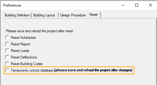
Typically, the data in database cannot be modified. This is to prevent accidental misuse. To make modifications, please go to ‘Setting’, ‘Preferences’, ‘Reset’, and check ‘Temporarily unlock database’.
To update the database, please make sure to save and reload the project after changes.
Shear Walls Tab
The members shown under this tab will be the candidates for sizing of shear wall calculations in LAVA.
Wood Shear Walls
.png) : Displays a sub-category of shear wall candidates that fit various seismic design categories.
: Displays a sub-category of shear wall candidates that fit various seismic design categories.
Usage: You can toggle Y (or N) to include (or exclude) a shear wall type into (or from) sizing candidates.
Mark on Plan: The type of a shear wall shown in model space.
Sides: If ‘1’ is input, shear wall symbol will be displayed on one side of wall; if ‘2’ is input, shear wall symbol will be displayed on both sides of wall.
Mark on Foundation: The type of a shear wall shown on foundation layout. Foundation layout is a future feature- not currently available.
Description in Calculation: The description of a shear wall type shown on Shear Wall Schedule in calcs report.
(E)Ck Basic Aspect Ratio: When subject to seismic loads, the limit of height-to-width (h/bs) ratio when modification of nominal shear capacity is not required per SDPWS 4.3.4.2.
(E)Ck Min Aspect Ratio: When subject to seismic loads, the limit of height-to-width (h/bs) ratio when a shear wall is no longer qualified per SDPWS Table 4.3.4. Sometimes this is referred to as Max aspect ratio.
(E)ASD (PLF): When subject to seismic loads, the ASD allowable unit shear capacity of a shear wall type.
(E)LRFD (PLF): Not applicable- LRFD currently not available.
(E)LSD (PLF): Not applicable- LSD currently not available.
(E)Stiffness: Stiffness of the wall for seismic loads, k/in.
(W)Ck Basic Aspect Ratio: When subject to wind loads, the limit of height-to-width (h/bs) ratio when modification of nominal shear capacity is not required per SDPWS 4.3.4.2.
(W)Ck Min Aspect Ratio: When subject to wind loads, the limit of height-to-width (h/bs) ratio when a shear wall is no longer qualified per SDPWS Table 4.3.4. Sometimes this is referred to as Max aspect ratio.
(W)ASD (PLF): When subject to wind loads, the ASD allowable unit shear capacity of a shear wall type.
(W)LRFD (PLF): Not applicable- LRFD currently not available.
(W)LSD (PLF): Not applicable- LRFD currently not available.
(W)Stiffness: Stiffness of the wall for wind loads, k/in.
Cost: Not applicable- pricing/cost is currently not available.
Fastener Spacing: The fastener spacing of a shear wall type shown on Shear Wall Schedule in calcs report.
Material Thickness: The material thickness of a shear wall type shown on Shear Wall Schedule in calcs report.
Stud Spacing: Stud spacing of a shear wall type. This is for reference only and displayed for informational purposes.
Upper Level Plate: The sill plate size of a shear wall type at levels other than ground level. This is for reference only and displayed for informational purposes.
Upper Level Nail: The sill plate nailing of a shear wall type at levels other than ground level. This is for reference only and displayed for informational purposes.
Foundation Level Plate: The sill plate size of a shear wall type at ground level. This is for reference only and displayed for informational purposes.
Foundation Level Nail: The sill plate anchorage of a shear wall type at ground level. This is for reference only and displayed for informational purposes.
Notes: This space is reserved for comments or notes for a shear wall type. This is for reference only and displayed for informational purposes.
Hardy Panel
Usage: You can toggle Y (or N) to include (or exclude) a hardy panel model into (or from) sizing candidates.
Group: Internal grouping of elements based on nominal widths. (For system use only; not displayed to users.)
Element: The name of a hardy panel model.
Framing: The type of a shear wall shown in model space.
Foundation: The type of a shear wall shown on foundation layout. Foundation layout is a future feature- not currently available.
fc: Concrete compressive strength f’c listed in MiTek catalog pages.
Weight: Weight of panel listed in MiTek catalog pages.
Height: Height of panel listed in MiTek catalog pages.
Length: Length of panel listed in MiTek catalog pages.
Ck: Applied vertical axial loads concurrent with the allowable shear load listed in MiTek catalog pages.
ASD-E: Allowable in-plane seismic shear load listed in MiTek catalog pages.
Drift-E: Drift under allowable in-plane seismic shear load listed in MiTek catalog pages.
Stiffness-E: Stiffness = shear / deflection, in kips/inch, calculated with seismic shear load and drift listed in MiTek catalog pages.
Tension-E: Uplift under allowable in-plane seismic shear load listed in MiTek catalog pages.
ASD-W: Allowable in-plane wind shear load listed in MiTek catalog pages.
Drift-W: Drift under allowable in-plane wind shear load listed in MiTek catalog pages.
Stiffness-W: Stiffness = shear / deflection, in kips/inch, calculated with wind shear load and drift listed in MiTek catalog pages.
Tension-W: Allowable in-plane seismic wind load listed in MiTek catalog pages.
Cost: Not applicable- pricing/cost is currently not available.
Connection to Framing: Quality of WS MiTek screws required in MiTek HFX installation details.
Connection to Foundation: Anchor rods, standard or high-strength.
Notes: This space is reserved for comments or notes for user. This is for reference only and displayed for informational purposes.
Simp Steel Strg
Not currently available.
Simp Wood Strg
.png)
: Displays a sub-category of Simpson Wood Strong-Wall candidates listed in Simpson Strong-Tie catalog.
Usage: You can toggle Y (or N) to include (or exclude) a WSWH model into (or from) sizing candidates.
Group: Internal grouping of elements based on nominal widths. (For system use only; not displayed to users.)
Element: The name of a WSWH model.
Framing: The type of a shear wall shown in model space.
Foundation: The type of a shear wall shown on foundation layout. Foundation layout is a future feature- not currently available.
fc: Concrete compressive strength f’c listed in Simpson Strong-Tie catalog pages.
Weight: Weight of panel listed in Simpson Strong-Tie catalog pages.
Height: Height of panel listed in Simpson Strong-Tie catalog pages.
Length: Length of panel listed in Simpson Strong-Tie catalog pages.
Ck: Applied vertical axial loads concurrent with the allowable shear load listed in Simpson Strong-Tie catalog pages.
ASD-E: Allowable in-plane seismic shear load listed in Simpson Strong-Tie catalog pages.
Drift-E: Drift under allowable in-plane seismic shear load listed in Simpson Strong-Tie catalog pages.
Stiffness-E: Stiffness = shear / deflection, in kips/inch, calculated with seismic shear load and drift listed in Simpson Strong-Tie catalog pages.
Tension-E: Uplift under allowable in-plane seismic shear load listed in Simpson Strong-Tie catalog pages.
ASD-W: Allowable in-plane wind shear load listed in Simpson Strong-Tie catalog pages.
Drift-W: Drift under allowable in-plane wind shear load listed in Simpson Strong-Tie catalog pages.
Stiffness-W: Stiffness = shear / deflection, in kips/inch, calculated with wind shear load and drift listed in Simpson Strong-Tie catalog pages.
Tension-W: Allowable in-plane seismic wind load listed in Simpson Strong-Tie catalog pages.
Cost: Not applicable- pricing/cost is currently not available.
Connection to Framing: Top connection hardware required in Simpson Strong-Tie installation details.
Connection to Foundation: Anchor rods required in Simpson Strong-Tie installation details.
Notes: This space is reserved for comments or notes for user. This is for reference only and displayed for informational purposes.
Hold-Downs
.png)
: Displays a sub-category of application of hold-downs. Please refer to Glossary for explanations of these terms.
.png)
: Displays a sub-category of installation conditions of hold-downs. These conditions are consistent with capacities listed in hardware catalogs (Simpson Strong-Tie).
Usage: You can toggle Y (or N) to include (or exclude) a hold-down type into (or from) sizing candidates.
Group: Internal grouping of elements based on nominal widths. (For system use only; not displayed to users.)
Element: The name of a hold-down type.
Framing: The type of a shear wall shown in model space.
Foundation: The type of a shear wall shown on foundation layout. Foundation layout is a future feature- not currently available.
Width: Minimum dimension of the stud/post in the direction of shear wall.
Depth: Minimum dimension of the stud/post perpendicular to the direction of shear wall.
ASD-E: Allowable seismic tension loads listed in Simpson Strong-Tie catalog pages. These values already considered duration factor, with no further increase allowed.
LRFD-E: Not applicable- LRFD currently not available.
Capacity: Not applicable- Capacity currently not available.
K/in: Stiffness of the connection assembly based on selected gap defined in the Hold Down settings.
ASD-W: Allowable wind tension loads listed in Simpson Strong-Tie catalog pages. These values already considered duration factor, with no further increase allowed.
LRFD-W: Not applicable- LRFD currently not available.
$/Unit: Not applicable- pricing/cost is currently not available
Connection to Framing: Connectors required when installed on wood members in Simpson Strong-Tie catalog.
Connection to Foundation: Connectors required when installed in concrete foundation.
Tie-Downs
Rod
.png)
: Displays a sub-category of installation conditions of tie-down rods.
Usage: You can toggle Y (or N) to include (or exclude) a tie-down rod into (or from) sizing candidates.
Mark on Plan: The type of a tie-down rod shown in model space.
Mark on Foundation: The type of a tie-down rod shown on foundation layout. Foundation layout is a future feature- not currently available.
Description in Calculation: The description of a tie-down rod type shown on Shear Wall Schedule - Hold Down Schedule in calcs report.
(E)Ck PostWidth: Minimum dimension of the stud/post in the direction of shear wall under seismic loads. This is for reference only. LAVA does not automatically check this requirement.
(E)Ck PostDepth: Minimum dimension of the stud/post perpendicular to the direction of shear wall under seismic loads. This is for reference only. LAVA does not automatically check this requirement.
(E)ASD Uplift: Allowable seismic tension loads listed in manufacturer’s catalog pages. These values already considered duration factor, with no further increase allowed.
(E)LRFD Uplift: Not applicable- LRFD currently not available.
(E)LSD Uplift: Not applicable- LSD currently not available.
(E)Stiffness (K/in): Stiffness of the wall for seismic loads, k/in.
(W)Ck PostWidth: Minimum dimension of the stud/post in the direction of shear wall under wind loads. This is for reference only. LAVA does not automatically check this requirement.
(W)Ck PostDepth: Minimum dimension of the stud/post perpendicular to the direction of shear wall under wind loads. This is for reference only. LAVA does not automatically check this requirement.
(W)ASD Uplift: Allowable wind tension loads listed in manufacturer’s catalog pages. These values already considered duration factor, with no further increase allowed.
(W)LRFD Uplift: Not applicable- LRFD currently not available.
(W)LSD Uplift: Not applicable- LSD currently not available.
(W)Stiffness (K/in): Stiffness of the wall for wind loads, k/in.
Cost: Not applicable- pricing/cost is currently not available
Min Post: Not applicable.
Post Area: The result of multiplying PostWidth and PostDepth.
Post Connection: Not applicable.
Foundation Connection: Tie-down rods required in manufacturer’s catalog.
Notes: This space is reserved for comments or notes for user. This is for reference only and displayed for informational purposes.
Rod Diameter: The diameter of a tie-down rod.
Materials Tab
This is a library of all the materials in LAVA. These materials are used in the Load Definitions and Load Assemblies.
.png)
These Materials can be seen in the Load Definitions.
If you want to Edit these Materials- follow these steps:
Unlock the database by going to Settings- Preferences- Reset- Temporarily Unlock Database.
Make the changes to the text or values.
Save the file to see the Materials show up in the Loads Definitions.
Note: These items can be adjusted only. You cannot add/delete any of the items at this time.
Beams Tab
The member sections shown under this tab will be the candidates for sizing of beam calculations in LAVA.
.png)
Beam Species .png) : Select a specific item from the drop-down menu to make modifications.
: Select a specific item from the drop-down menu to make modifications.
Grade .png) : Select a specific item from the drop-down menu to make modifications.
: Select a specific item from the drop-down menu to make modifications.
Lumber/Timber
.png)
(Image for reference)
USAGE: You can toggle Y (or N) to include (or exclude) a section into (or from) sizing candidates.
BMGROUP: Internal grouping of elements based on nominal widths. (For system use only; not displayed to users.)
BMSIZE: The size of a section shown in LAVA calculation.
BMSIZEDESC: The description of a section shown in the model space in Building Layout tab.
WIDTH: The width of a section in inch.
DEPTH: The depth of a section in inch.
WT: The weight of a section in pounds per linear foot (plf). Based on specific gravity adjusted to 12% in use moisture.
Cfb: The size factor CF for reference bending design value.
Cfb2: The flat use factor CFU for reference bending design value.
Cfe: The flat use factor CFU for reference on all E values.
Cft: The size factor CF for reference tension design value.
Cfc: The size factor CF for reference compression design value.
AREA: The area of a section in inch2.
S: The section modulus of a section in inch3.
I: The moment of inertia of a section in inch4.
Fb_Asd: Reference bending design value in psi.
NA1: Not Applicable (Not Used)
Fc1_Asd: Reference compression design value perpendicular to grain in psi.
NA2: Not Applicable (Not Used)
Fv_Asd: Reference shear design value in psi.
E_Asd: (Etrue) Reference modulus of elasticity in x106 psi.
Eaap_Asd: (Eapparent) Apparent modulus of elasticity in x106 psi.
E_Asd: Reference modulus of elasticity in x106 psi.
Eaap_Asd: Reference modulus of elasticity in x106 psi.
Emin_Asd: Reference modulus of elasticity for beam stability calculation in x106 psi.
G: Specific gravity
Fb_Asd_y: Reference bending design value bending about y-y axis, psi.
Fc1_Asd_y: Reference compression design value parallel to grain, psi.
Fv_Asd_y: Reference shear design value parallel to grain (horizontal shear), psi.
E_Asd_y: (Etrue) Reference modulus of elasticity in x106 psi.
Eapp_Asd_y: (Eapp) Apparent modulus of elasticity in x106 psi.
Emin_Asd_y: Reference of elasticity of beam stability, psi.
Ft_Asd: reference tension design value in psi.
Fcc_Asd: Reference compression design value parallel to grain in psi.
GLB-Std/GLB-IJC
.png)
USAGE: You can toggle Y (or N) to include (or exclude) a section into (or from) sizing candidates.
BMGROUP: Internal grouping of elements based on nominal widths. (For system use only; not displayed to users.)
BMSIZE: The size of a section shown in LAVA calculation.
BMSIZEDESC: The description of a section shown in the model space in Building Layout tab.
WIDTH: The width of a section in inch.
DEPTH: The depth of a section in inch.
WT: The weight of a section in pounds per linear foot (plf). Based on specific gravity adjusted to 12% in use moisture.
Cv_l: Volume factor based on the worst case length.
Cv_d: (12/d)1/x per Equation 5.3-1 in National Design Specification for Wood Construction (NDS).
Cv_b: (5.125/b)1/x per Equation 5.3-1 in National Design Specification for Wood Construction (NDS).
AREA: The area of a section in inch2.
S: The section modulus of a section in inch3.
I: The moment of inertia of a section in inch4.
Fb_Asd: Reference bending design value (bottom of beam stressed in tension) in psi. Loaded perpendicular to wide faces of laminations.
Fb_neg_Asd: Reference bending design value (top of beam stressed in tension) in psi. Loaded perpendicular to wide faces of laminations.
Fc1_Asd: Reference compression design value perpendicular to grain in psi. Loaded perpendicular to wide faces of laminations.
Fc2_Asd: Reference compression design value parallel to grain in psi. Loaded perpendicular to narrow faces of laminations.
Fv_Asd: Reference shear design value in psi. Loaded perpendicular to wide faces of laminations.
E_Asd: (Etrue) Reference modulus of elasticity in x106 psi. Loaded perpendicular to wide faces of laminations.
Eaap_Asd: (Eapparent) Apparent modulus of elasticity in x106 psi. Loaded perpendicular to wide faces of laminations.
Emin_Asd: Reference modulus of elasticity for beam stability calculation in x106 psi. Loaded perpendicular to wide faces of laminations.
G: Specific gravity
Fb_Asd_y: Reference bending design value in psi. Loaded parallel to wide faces of laminations.
Fc1_Asd_y: Reference compression design value perpendicular to grain in psi. Loaded parallel to wide faces of laminations.
Fv_Asd_y: Reference shear design value in psi. Loaded parallel to wide faces of laminations.
E_Asd_y: (Etrue) Reference modulus of elasticity in x106 psi. Loaded parallel to wide faces of laminations.
Eapp_Asd_y:(Eapparent) Apparent modulus of elasticity in x106 psi. Loaded parallel to wide faces of laminations.
Emin_Asd_y: Reference modulus of elasticity for beam stability calculation in x106 psi. Loaded parallel to wide faces of laminations.
Ft_Asd: reference tension design value in psi.
Fcc_Asd: Reference compression design value parallel to grain in psi.
LSL/LVL/PSL
.png)
USAGE: You can toggle Y (or N) to include (or exclude) a section into (or from) sizing candidates.
BMGROUP: Internal grouping of elements based on nominal widths. (For system use only; not displayed to users.)
BMSIZE: The size of a section shown in LAVA calculation.
BMSIZEDESC: The description of a section shown in the model space in Building Layout tab.
WIDTH: The width of a section in inch.
DEPTH: The depth of a section in inch.
WT: The weight of a section in pounds per linear foot (plf).
NA: Not Applicable (Not Used)
FDX: The volume factor in joist/beam orientation.
FDY: The volume factor in face/plank orientation.
AREA: The area of a section in inch2.
S: The section modulus of a section in inch3.
I: The moment of inertia of a section in inch4.
Fb_Asd: Reference bending design value (bottom of beam stressed in tension) in psi. Loaded in joist/beam orientation.
Fb_neg_Asd: Reference bending design value (top of beam stressed in tension) in psi. Loaded in joist/beam orientation.
Fc1_Asd: Reference compression design value perpendicular to grain in psi. Loaded in joist/beam orientation.
Fc2_Asd: Reference compression design value parallel to grain in psi.
Fv_Asd: Reference shear design value in psi. Loaded in joist/beam orientation.
E_Asd: (Etrue) Reference modulus of elasticity in x106 psi. Loaded in joist/beam orientation.
Eaap_Asd: (Eapparent) Apparent modulus of elasticity in x106 psi. Loaded in joist/beam orientation.
Emin_Asd: Reference modulus of elasticity for beam stability calculation in x106 psi. Loaded in joist/beam orientation.
G: Shear modulus of elasticity in x106 psi.
Fb_Asd_y: Reference bending design value in psi. Loaded in face/plank orientation.
Fc1_Asd_y: Reference compression design value perpendicular to grain in psi. Loaded in face/plank orientation.
Fv_Asd_y: Reference shear design value in psi. Loaded in face/plank orientation.
E_Asd_y: (Etrue) Reference modulus of elasticity in x106 psi. Loaded in face/plank orientation. This value is not typically provided by manufacturer and is back calculated from the modulus of elasticity that is provided.
Eapp_Asd_y: (Eapparent) Apparent modulus of elasticity in x106 psi. Loaded in face/plank orientation. This value is not typically provided by manufacturer and is back calculated from the modulus of elasticity that is provided.
Emin_Asd_y: (Emin) Reference modulus of elasticity for beam/column stability calculation in x106 psi. Loaded in face/plank orientation.
Ft_Asd: reference tension design value in psi.
Fcc_Asd: Reference compression design value parallel to grain in psi.
BMSIZE: The size of a section shown in LAVA calculation and model space.
DEPTH: The depth of a section in inch.
WIDTH: The width of a section in inch.
WIDTHBOT: The bottom flange width of a section in inch.
THICKNESS: The thickness of metal in inch.
LIPS: The lip/return length of C channel.
RADIUS: The radius of C channel bends.
E: Reference modulus of elasticity in x106 psi.
Fy: The yield stress of metal in psi.
Fu: The tensile stress of metal in psi.
miu: Poisson’s ratio.
HoleDep: Punchout length in inch.
HoleWid: Punchout width in inch.
Cornerr: Punchout corner radius.
HoleSpac: Punchout spacing in inch.
Steel
USAGE: You can toggle Y (or N) to include (or exclude) a section from sizing candidates.
BMSIZE: The size of a section shown in LAVA calculation and model space.
DEPTH: The depth of a section in inch.
DepthNom: The nominal depth of a section in inches.
WIDTH: The width of a section in inch.
WidthNom: Internal grouping of elements based on nominal widths. (For system use only; not displayed to users.)
WebThick: The thickness of web in inch.
FlangeThick: The thickness of flange in inch.
Area: The area of a section in inch2.
Weight: The weight of a section in pounds per linear foot (plf).
E: Modulus of elasticity in psi.
Fy: The specified minimum yield stress of metal in psi.
Fu: The minimum tensile stress of metal in psi.
bovert: Compact section criteria (bf/2tf) of a section.
hovert: Compact section criteria (h/tw) of a section.
Ix: Moment of inertia of a section about X-axis in inch4.
Sx: Elastic section modulus of a section about X-axis in inch3.
Rx: Radius of gyration of a section about X-axis in inch.
Zx: Plastic section modulus of a section about X-axis in inch3.
Iy: Moment of inertia of a section about Y-axis in inch4.
Sy: Elastic section modulus of a section about Y-axis in inch3.
Ry: Radius of gyration of a section about Y-axis in inch.
Zy: Plastic section modulus of a section about Y-axis in inch3.
rts: Effective radius of gyration of a section in inch.
ho: Distance between centroid of flanges of a section in inch.
J: Torsional moment of inertia of a section in inch4.
Cw: Warping constant of a section inch6.
Loads
You can view and edit the load types and load combinations under this tab.
Note: To Add, Edit or Delete - you need to go to Settings- Preferences- Reset- Temporarily Unlock Database
Load Groups: LAVA categorized the load combinations into three load groups: IBC ASD Regular, IBC ASD Deflection, and IBC ASD Special Seismic (with overstrength Omega factor). After selecting a load group, you can toggle Y or N under each type of structural elements to allow certain load combination to be considered or not in the analysis of these elements.
.png)
Load Combinations: Displays all the load combinations under the Load Groups you previously selected. After selecting a load combination, you can view and edit the factors for each load type.
.png)
Load Types: Displays the basic load types in LAVA, including D (dead load), L (live load), Lr (roof live load), Sn (snow load), W(+) (wind load in positive direction of X or Y axis), W(-) (wind load in positive direction of X or Y axis), E (seismic load).
Load Definitions: This groups the loads together within each Load Type. For example, the dead loads (D) in the Floor system contain carpet, padding, sheeting, floor joists, etc.. These are all grouped together in the Load Definition.
Note: Load Types and Load Definitions work together. Load Types filters the display of the Load Definitions.
Load Assemblies: This grouping combines the Load Definitions to complete the loads. For example, you have dead loads and live loads on your floor system and the Load Assembly combines these loads together.
After you temporarily unlock the database, these options will show up, ‘Add’, ‘Edit’, and ‘Del’.
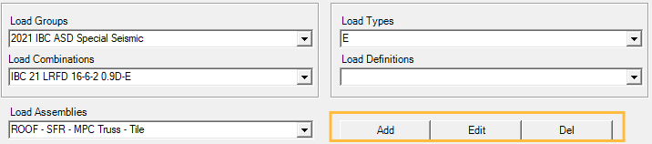
These will allow you to add, edit, or delete a load group, load type, load combination, load definition, or a load assembly.
Deflections
You can view and edit the limits on deflection in analysis of structural elements. LAVA has predefined several deflection limits shown in the sub-window.
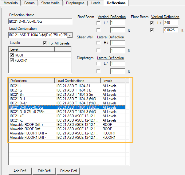
Deflection Name: Displays the name defined for a deflection limit.
Load Combination: Displays the load combination associated with the deflection limit.
Levels: You can choose which levels this deflection limit will apply to.
Vertical Deflection / Lateral Deflection: LAVA provides two ways to limit the deflections of structural elements: in relation to the element dimension, or absolute deflection value in feet.
Add Defl: You can make modifications to the above options, and click this button to save it as a new deflection limit.
Edit Defl: You can make modifications to the above options, and click this button to save the edit to an existing deflection limit.
Delete Defl: You can click this button to remove the selected existing deflection limit.