The Edit Group let you make changes to Beams, Shear Walls, and Bearing Walls directly in the graphical view. This feature streamlines editing by letting you select elements on the plan and adjust their properties all in one place.
Overview
Edit Group can be activated by right click in model space or navigation window after group selection.
With the Edit Group, you can:
Select elements visually in the plan view or from the sidebar list
Edit multiple items at once
Open an editing dialog that shows all adjustable parameters
These tools support Beams, Bearing Walls and Shear Walls. Use right click to activate ‘Edit Group‘ command after your selection.
Selecting Elements
You can select items in two ways:
Graphical selection: Press Ctrl on keyboard to select multiple items with single left click on mouse. Or click and drag to draw a box around the elements you want to select on the plan view.
Sidebar selection: Use the list on the left side to choose specific elements.
Selected items will highlight in yellow so you can easily see what's included.
If mixed items are included in the selection, right click any one of the items whose type you wish to edit. For example, if both beams and walls are included in selection at the same time, and you only wish to group edit the beams, simply right click any one of the beams, and select Edit Group in the menu.
Editing Beams
Once you have selected the beams you want to modify:
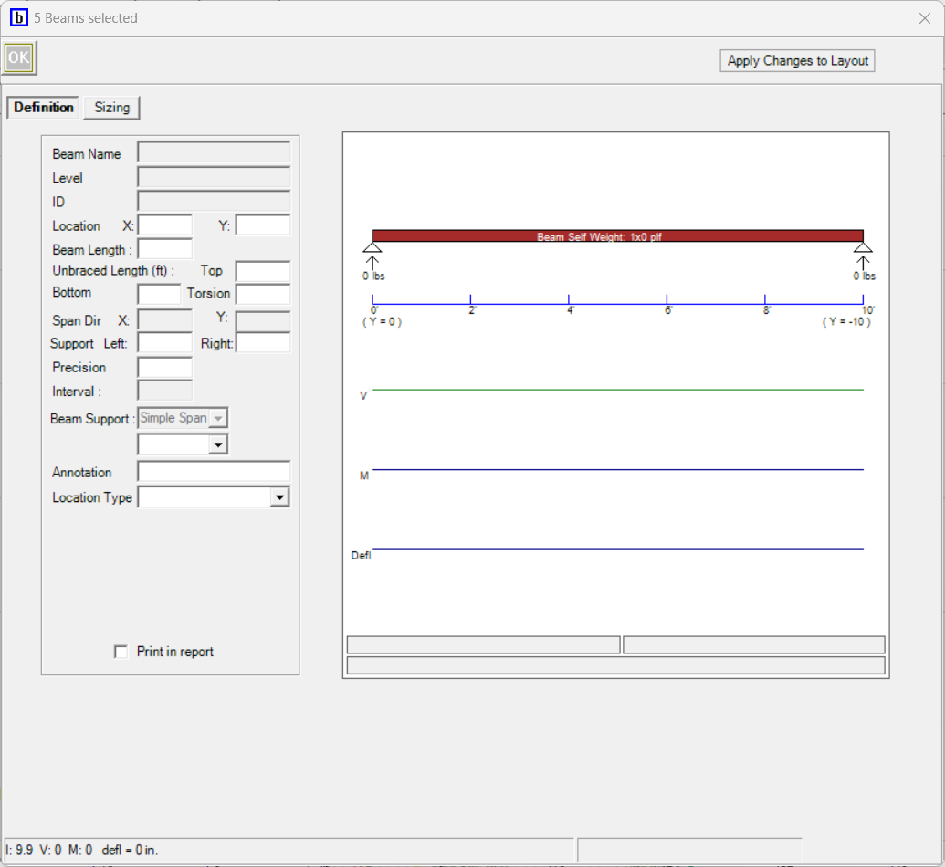
Right click and select Edit Group.
A modified version of Beams Design dialog will open. The title of the dialog will display the number of elements selected. You do not have to fill out every field. Please note: if a field is left blank, revisions will not be made to any of the elements regarding that specific field.
.png)
Review and adjust the available parameters. These include (but may not be limited to):
Location (X and Y)
Beam Length
Unbraced Length
Support (Left and Right)
Precision
Drop Beam, Flush Beam, Header (notation purposes only)
Annotation
Location Type (Roof/Floor)
Print Report
Beam Type
Beam Material and species
Beam Width and Depth filter
Beam AAF values
Multi Beam amount
Specific Beam Size
Support settings
Multi Post amount
Effective unbraced length for support post
Unbraced Axis for support post
Post Type
Post Material and species
Post Depth filter
Post AAF values
Wall Plate Bearing conditions
Specific Post Sizes
When you're finished, press ‘Apply Changes to Layout’ to confirm your changes, or press ‘OK’ to confirm changes and close the dialog. The plan view will update to reflect your edits. Please review parameters carefully before applying changes, currently there is no undo function for Edit Group.
Note: To turn off Print in Report- click the Print in report- turn on and turn off then click OK.
Editing Bearing Walls
The process is similar for Bearing Walls:
Select the Bearing Walls graphically or from the sidebar.
Right click and select Edit Group.
A modified version of Bearing Wall Design dialog will open. The title of the dialog will display the number of elements selected. You do not have to fill out every field. Please note: if a field is left blank, revisions will not be made to any of the elements regarding that specific field.
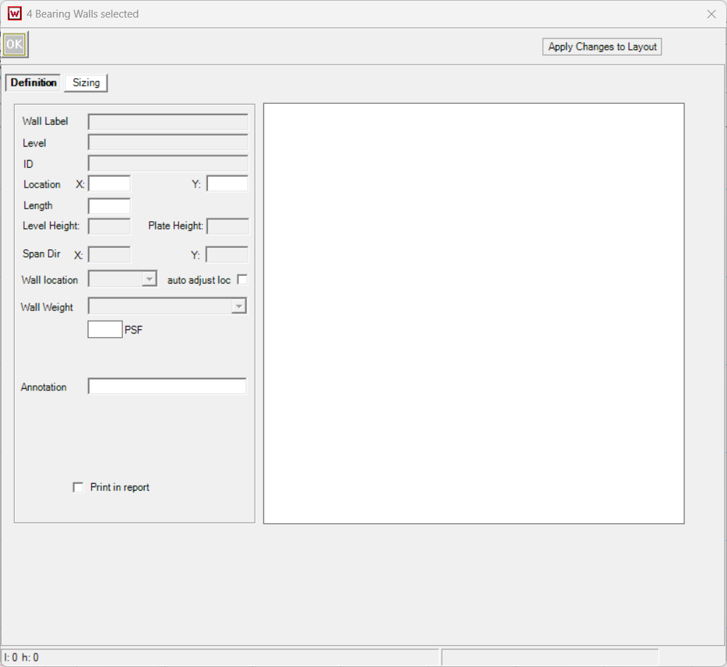
Review and adjust the available parameters. These include (but may not be limited to):
Location (X and Y)
Length
Wall location and Wall Weight
Sheathing Side
Annotation
Print in report- Turn on Globally in Setting- Preferences Building Layout
Stud Type. Once selected, the rest of the field will be updated accordingly.
Height
Cr
Count
Stud Spacing/Size
Allowable Adjustment Factor, AAF values
Deflection limit L/x
Editing Shear Walls
The process is similar for Shear Walls:
Select the Shear Walls graphically or from the sidebar.
Right click and select Edit Group.
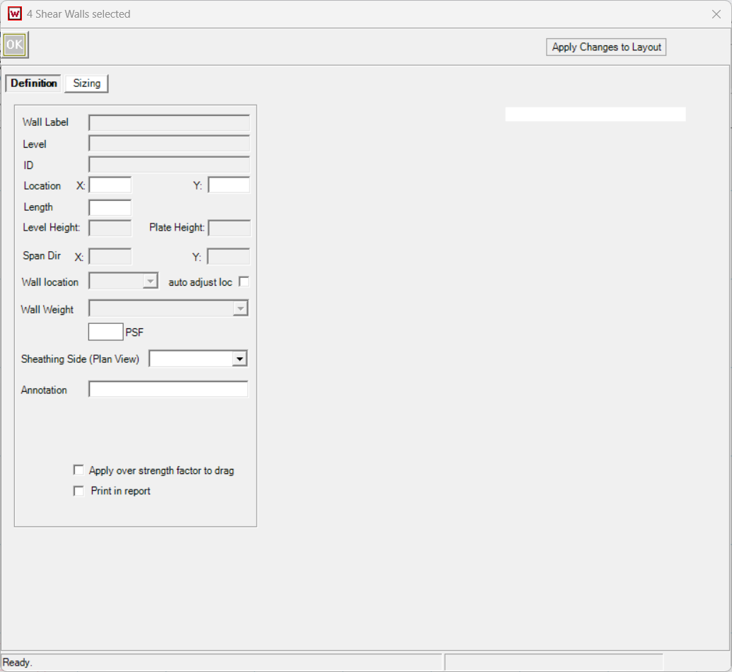
A modified version of Shear Wall Design dialog will open, with only ‘Sizing’ tab visible. The title of the dialog will display the number of elements selected. You do not have to fill out every field. Please note: if a field is left blank, revisions will not be made to any of the elements regarding that specific field.
.png)
Review and adjust the available parameters. These include (but may not be limited to):
Location (X and Y)
Length
Wall location and Wall Weight, click on/off auto adjust loc to activate these fields
Sheathing Side
Annotation
Apply Overstrength factor to Drag
Print in report- click on/off to turn off
Wall Type. Once selected, the rest of the field will be updated accordingly. ‘Auto Adjust Size’ will be checked automatically
Shear Wall Height and Applied Load Height
Allowable Adjustment Factor
Auto Adjust Size. If checked, Wall Size will be available to edit
Hold-down Type. Once selected, the rest of the field will be updated accordingly. ‘Auto Adjust Size’ will be checked automatically
Hold-down installation condition
Edge Offset Dist.
AAF values
Auto Adjust Size. If checked, Hold Down Size will be available to edit
Support settings
Multi Post amount
Unbraced length for support post
Unbraced Axis for support post
Post Type
Post Material and species
Post Depth filter
Post AAF values
Wall Plate Bearing conditions
Specific Post Sizes
When you're finished, press ‘Apply Changes to Layout’ to confirm your changes, or press ‘OK’ to confirm changes and close the dialog. The plan view will update to reflect your edits. Please review parameters carefully before applying changes, currently there is no undo function for Edit Group.
Note: To turn off Print in Report and/or Apply Overstrength factor to drag- click the Print in report- turn on and turn off then click OK.
Tips
You can select multiple items of the different types at once for batch editing. But you can only edit one type at a time. Simply right click an element of the type you want to edit, and select ‘Edit Group’.
Deselection is easy: click away from the plan or use the clear selection option.
Always review parameters carefully before applying changes, currently there is no undo function.