LAVA provides a comprehensive insight behind the calculation. All of the loads and reactions can be reviewed under Calculation Log tab.
Elements
Shear Walls
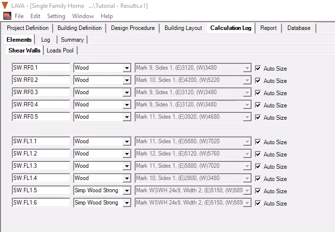
The first screen shows all of the shear walls in the project, type and design information.
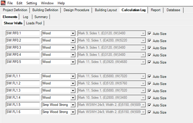
You can review the current design of all shear wall elements. To make revisions on this tab, uncheck ‘Auto Size‘, and manually select shear wall type as needed.
Loads Pool
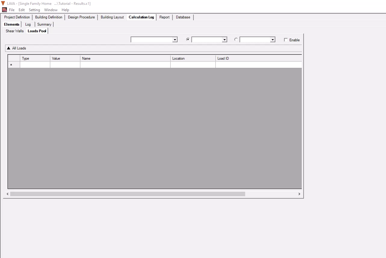
The loads pool shows all of the gravity loads as they are transferred down the building. Under Loads Pool tab, reactions of all elements will be displayed.
It will be empty when you first open it, this is to save memory until it’s needed.
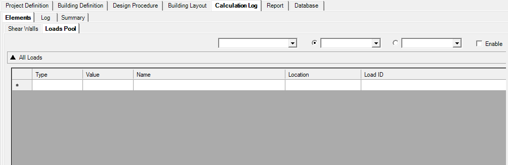
To enable this feature, check ‘Enable’ on the right side, and run Analyze, and return to this tab.
Log
Log tab shows the background calcs of all elements, including code check and deflection calcs, are all displayed for your review.
This log will be empty when you first open it, this is to save memory until it’s needed.
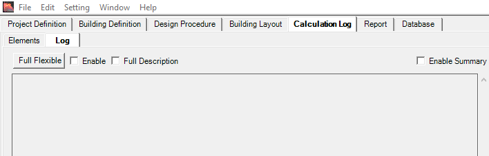
To enable this feature, check ‘Enable’ and ‘Full Description’. If ‘Enable Summary’ is checked, a third tab ‘Summary’ will appear, with lateral loading details, including diaphragm loading, wind and seismic analysis, displayed for your review. Run Analyze, and return to this tab, and press ‘Full Flexible‘.
Flexible Diaphragms Summary
This is the Flexible diaphragm summary that shows details floor by floor of each shear wall based on flexible diaphragm analysis. This summary will be shown for all analysis selected because LAVA always runs a flexible diaphragm analysis at the very beginning as a first step to get to further analysis- see analysis steps further here.
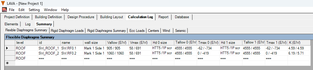
level: This refers to the floor level.
id: This is the internal name used to track the shear wall.
name: This is the shear wall name presented in the interface and report.
wall size: This is the shear Wall design selected.
V allow (E/W): This is the capacity of the selected shear wall (displayed as factored by governing load combination).
V Max (E/W): Maximum shear calculated based on the flexible analysis (displayed as factored by governing load combination). Note: if rigid diaphragm is chosen as the analysis method- refer to the Rigid Diaphragm Summary to find the design shear load as this is flexible shear is shown for reference.
Hd 0 Size: Hold-down selected for the left side of the wall.
T0 allow (E/W): Allowable Tension capacity provided by the hold-down on the left side of the wall.
Tmax 0 (E/W): Maximum tension in the right side of the wall (displayed as factored by governing load combination).
Hd 1 Size: Hold-down selected for the right side of the wall.
T1 allow (E/W): Allowable Tension capacity provided by the hold-down on the right side of the wall.
Tmax 1 (E/W): Maximum tension in the right side of the wall (displayed as factored by governing load combination).
K (E/W): Calculated stiffness of the shear wall.
Rigid Diaphragm Summary
This is the Rigid diaphragm summary that shows details floor by floor of each shear wall based on rigid diaphragm analysis. This summary will be shown only when Rigid analysis or Envelope is selected.
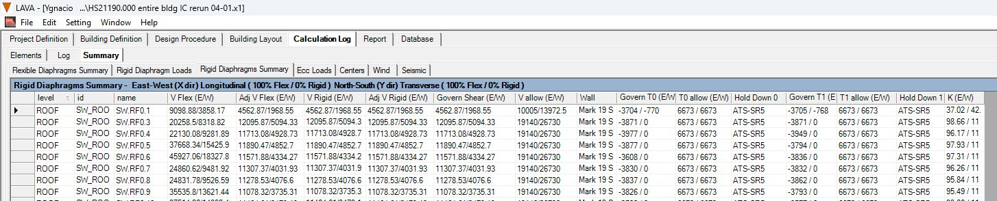
level: This refers to the floor level.
id: This is the internal name used to track the Shear wall.
name: This is the Shear wall name presented in the interface and report.
V Flex (E/W): Maximum shear calculated based on the flexible analysis.
Adj VFlex (E/W): This is the shear that governs based on the selected analysis method. If Rigid analysis is selected, the shear is adjusted to match V Rigid and that is displayed here. If Envelope is selected, the shear will be shown based on the highest shear between Flex and Rigid. (Displayed as factored by governing load combination).
V Rigid (E/W): Maximum shear calculated based on the rigid analysis (displayed as factored by governing load combination).
Adj V Rigid (E/W): This is the shear that governs based on the selected analysis method. If Flexible analysis is selected, the shear is adjusted to match V Flex and that is displayed here. If Envelope is selected, the shear will be shown based on the highest shear between Flex and Rigid. (Displayed as factored by governing load combination).
Govern Shear (E/W): This is the shear value that governs for the design (displayed as factored by governing load combination).
V allow (E/W): This is the capacity of the selected shear wall.
Wall: This is the wall that was selected to meet the design.
Govern T0 (E/W): Tension in the left side of the wall.
T0 allow (E/W): Allowable Tension capacity provided by the hold-down on the left side of the wall.
Hold Down 0: Hold-down selected for the left side of the wall.
Govern T1 (E/W): Tension in the right side of the wall.
T1 allow (E/W): Allowable Tension capacity provided by the hold-down on the right side of the wall.
Hold Down 1: Hold-down selected for the right side of the wall.
K (E/W): Calculated stiffness of the shear wall.