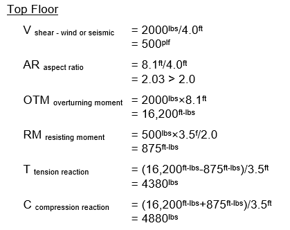
LAVA Design Example with Shear Walls Considered on a Floor-By-Floor Basis
Design example is for wind or seismic and without load factors.
This is intended to demonstrate only the engineering mechanics of shear wall design and how LAVA applies and calculates the loads.
.jpg)
Design Assumptions:
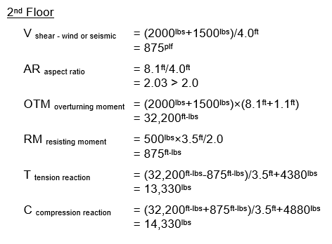
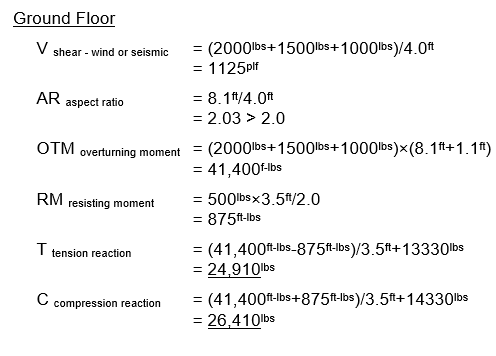
Lateral forces distribute to the shear walls from the diaphragms, therefore a wall directly below another may not resist the total lateral load of the wall above.
Lateral loads are applied at the sheathing elevation. Lateral drift due to the floor framing system is negligible. Gravity loads pass through the shear wall with only dead load being considered as contributing to resisting overturning.
Aspect ratio is computed from top of sheathing to top of plate above, unless a connection designed for the load on the wall occurs at a lower point.