Shear Lines are part of the lateral load resisting system in LAVA. Please see below for a couple properties of shear lines:
Lateral loads are:
Generated by diaphragm
Collected by shear lines
Distributed to and resisted by shear walls
.png)
There are two directions in the lateral systems in LAVA, X direction and Y direction.
The lateral elements are all associated with either and only one direction.
The two directions (X & Y) are analyzed separately. For example, a diaphragm modeled in X direction has nothing to do with the shear walls or shear lines in Y direction, so to generate and apply lateral loads to shear wall or shear line in Y direction, you must model diaphragms in Y direction..png)
How to Model Shear Lines in LAVA
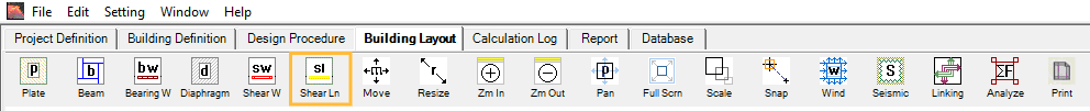
To model a shear line, click on toolbar .png) to start drawing shear lines in the model space. There is also a keyboard shortcut ‘L’ to activate this drawing command. Press the left button of mouse at the corner of an area of shear line and then release at the diagonal opposite corner of that area in the model space to model a shear line. If the shear line’s X-dimension (or ‘Width’) is longer than the Y-dimension (or ‘Height’), the shear line will be designated as a shear line in X direction; If the shear line’s X-dimension (or ‘Width’) is shorter than the Y-dimension (or ‘Height’), the shear line will be designated as a shear line in Y direction.
to start drawing shear lines in the model space. There is also a keyboard shortcut ‘L’ to activate this drawing command. Press the left button of mouse at the corner of an area of shear line and then release at the diagonal opposite corner of that area in the model space to model a shear line. If the shear line’s X-dimension (or ‘Width’) is longer than the Y-dimension (or ‘Height’), the shear line will be designated as a shear line in X direction; If the shear line’s X-dimension (or ‘Width’) is shorter than the Y-dimension (or ‘Height’), the shear line will be designated as a shear line in Y direction.
Navigating the Shearline Design Dialog
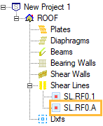
Double-click the shear line symbol .png) in model space, or double-click the Shear Line Name in the navigation list on the left:
in model space, or double-click the Shear Line Name in the navigation list on the left:
The design dialog of shear line will pop up:
.png)
.png "image(583).png") : Click ‘OK’ button to save any edit/input and close the window.:
: Click ‘OK’ button to save any edit/input and close the window.:
.png)
: Click on the top drop-down menu to quickly navigate all shear lines at this level. The left/right arrows allow you to also move to the previous/next shear line element.
.png "image(585).png") : Click ‘Apply Changes to Layout’ button to save any edit/input.
: Click ‘Apply Changes to Layout’ button to save any edit/input.
Definition Tab
.png)
Name: Displays the shear line name. LAVA initially assign a name by default for shear line element. You can edit the name, press .png) , and it will be displayed on the navigation list on the left.
, and it will be displayed on the navigation list on the left.
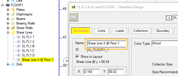
ID: Displays the internal ID of the shear line in program. This information cannot be altered.
Show in Layout: If you do not wish to show this shear line in model space, you can uncheck this option.
X (or Y): Displays the coordinates of the top-left end of this shear line in the model space.
Width: Displays the dimension of the shear line in X direction.
Height: Displays the dimension of the shear line in Y direction.
Label Location: You can choose how to display shear line symbol in model space in the drop-down menu:
Top/Left: Shear line bubble symbol is located at left or top of the shear line
.png)
Bottom/Right: Shear line bubble symbol is located at right or bottom of the shear line
.png)
Both Sides: Shear line bubble symbols are located at both ends of the shear line
.png)
Distribute by: LAVA allows two ways to distribute shear force among associated shear walls: Capacity (by default), or Stiffness. If the shear is distributed by stiffness, the analysis will be done per Special Design Provision For Wind And Seismic 4.3.3.4.1; if the shear is distributed by stiffness, the analysis will be done per SDPWS (Special Design Provision For Wind And Seismic) 4.3.3.4.1; the shear is distributed by capacity, the analysis will be done per SDPWS 4.3.3.4.1 Exception 1.
These are the options for the Shear Lines.
Conn Type: There are two major types of connections; Wood hold downs or Tie Rods. Based on your selection, this will filter the options you see for the type of connection. For Wood connection type, this describes the framing gap to calculate the stiffness of the connection. Most typically for a 16” Floor to Floor gap with 0.50 Specific Gravity option- this would be selected for Shear Lines with 11-7/8" I-joist floor framing including framing and finish layers.
.png)
(Shear Line Connection not shown in this image- just shown for reference of framing).
Collector Size: You can designate a specific collector size. If left blank, LAVA will display the recommended collector size after a full structure analyze.
Size Recommendation: After a full structure analyze, the recommended collector size will be displayed here.
Calculation of collector and shear distribution result is displayed at the sub window below Size Recommendation.
Links Tab
.png)
Links from Diaphragms and Shear Walls: Displays the elements (diaphragms at the same level or shear walls from upper level) that apply loads to this shear line.
Links to Shear Walls: Displays the shear walls that are subject to the loads distributed by this shear line.
This tab cannot be edited.
Loads Tab
This tab displays the loading information in the background calculation. This is helpful to verify calculation for loading or results. The values in this tab are all unfactored.
.png)
There are two blocks of data.
The first block is the loading applied to this shear line.
The second block is the reaction of this shear line.
This tab cannot be edited.
Collectors Tab
This tab displays the calculation of the drag force within this shear line.
.png)
X (or Y): Displays the coordinates of the top-left end of this shear line in the model space.
Width: Displays the dimension of the shear line in X direction.
Height: Displays the dimension of the shear line in Y direction.
The drag force calculation is displayed on the sub window below Height.
The maximum drag force, key section points, and drag diagram are displayed on the sub window on the right.
This tab cannot be edited.
Boundary Tab
.png)
Accept only the loads within the boundary from above level: By default, this item is unchecked, and all the upper-level shear walls within the region shown below (infinity to the left and to the right) will apply their reaction to this shear line.
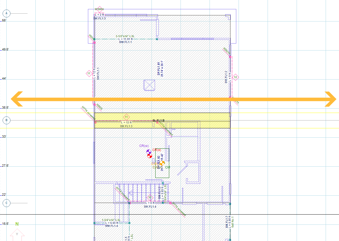
If this item is checked, only the upper-level shear walls within the rectangular area of this shear line (the yellow highlight when the shear line is selected) will apply their reaction to this shear line.
.png)
Report Tab
.png)
Include full details in report: By default, this item is unchecked, and only the result of the drag analysis will be included in the final report:
.png)
If this item is checked, a detailed drag analysis will be included in the final report:
.png)
Use as sample in report: To facilitate an external audience (such as a peer reviewer or city plan checker) to understand the distribution of shear loads in LAVA, you can include ‘Analysis Method’ into your final report under ‘Report’ tab:
.png)
And LAVA will include a detailed step-by-step procedure to demonstrate how shear load is calculated and distributed, including drag force analysis and a shear wall calculation as a ‘sample’. By default, LAVA will use the first shear line at FLOOR1 level as a sample. If you would like a specific shear line to be the sample, please check ‘Use as sample in report’ under ‘Report’ tab:
.png)
Please note: LAVA will only use one shear line as a sample. If you check this item, all previous chosen sample shear line will be disregarded.
Misc Tab
.png)
Over Strength Factor: If this shear line must be analyzed with overstrength factor, please input the factor at the field in front. By default, this field is blank.
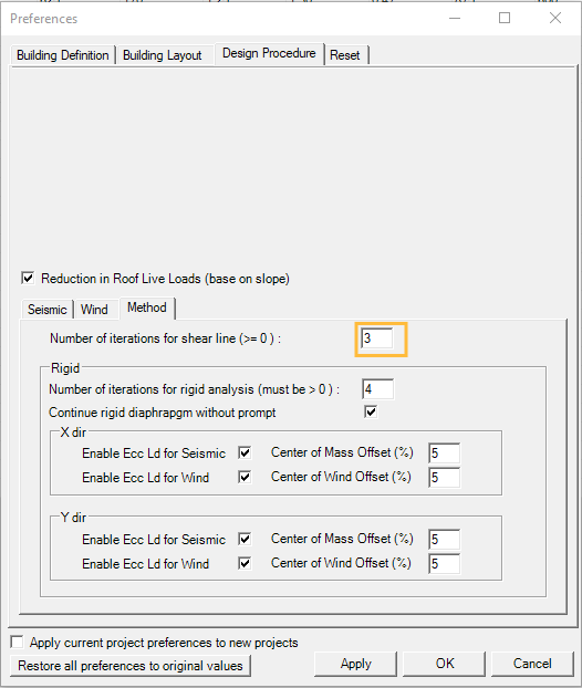
Number of iterations: If a shear line distributes shear by stiffness, you can specify how many iterations are required. If this field is left blank, LAVA will use the default iteration value defined in ‘Preference’ - ‘Design Procedure’ - ‘Method’: