In this part of tutorial, we will run the full structure analysis and review the results. Please continue working with the tutorial file that we used in ‘Drawing the Lateral System’ section. Or you can download the file at the end of ‘Drawing the Lateral System’ page and start from there.
Prefer to watch instead? You can also follow along with our step-by-step video tutorials.
Full Structure Analyze
After the modeling process is done,
Click Analyze
.png "image(564).png") button on Tool bar to run full structure analysis.
button on Tool bar to run full structure analysis.

A status update will pop up and show the process. If there is a model failure, it is helpful to see which element the process gets stuck at, and you can go to that specific element for trouble shooting.
.png "image(542).png")
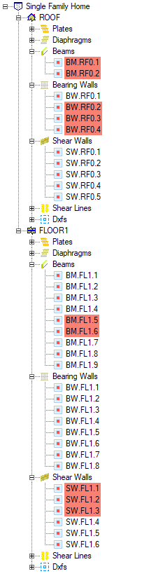
After the analysis is done, the navigation sub window will be updated.
The members highlighted in red fail the capacity check.
Review Beam Design
We can review and update the members that are failing.
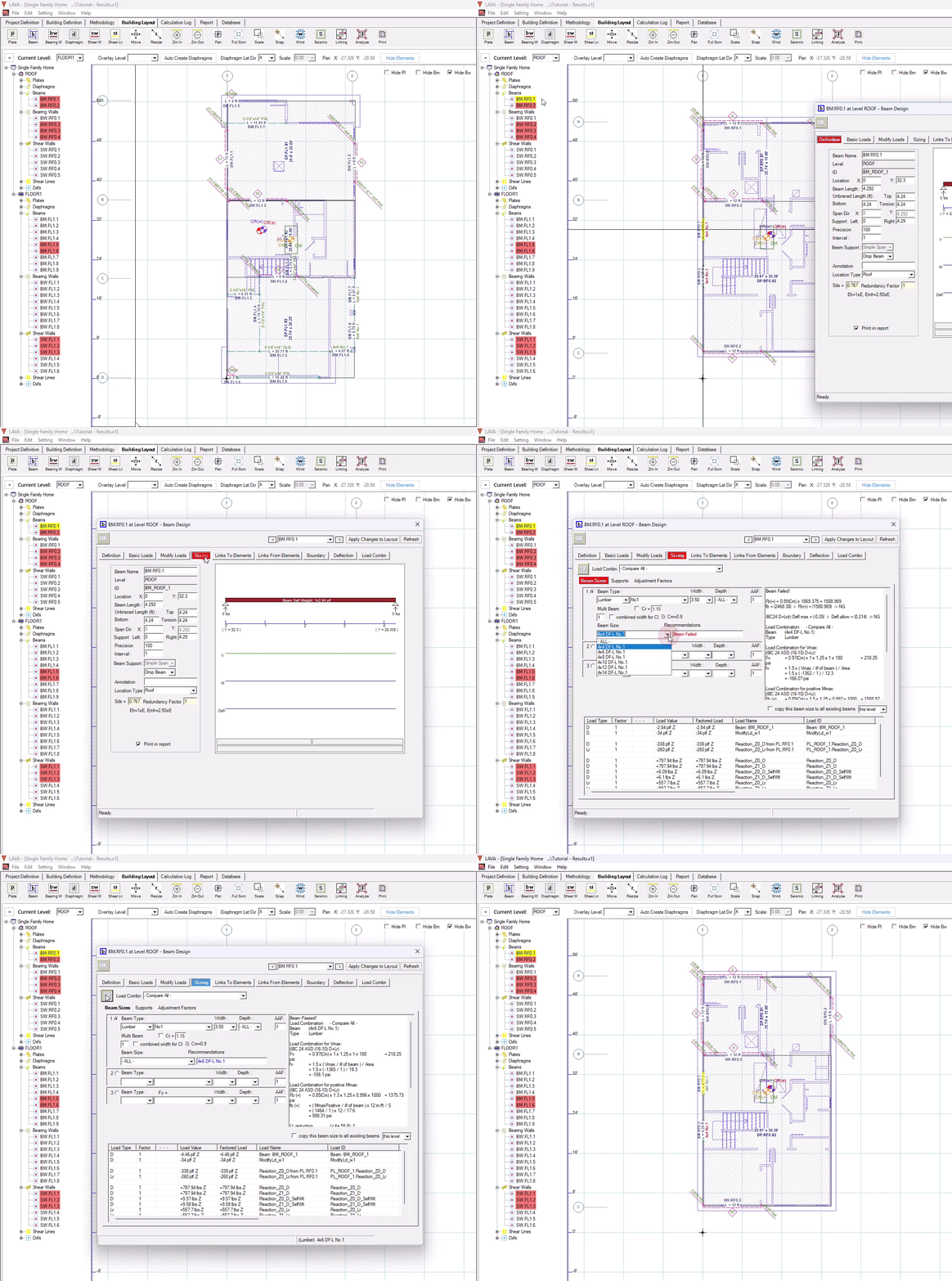
Double-click BM.RF0.1 to open design dialog
Go to ‘Sizing’ tab. It shows the previously designated size is not sufficient. The window on the right side shows the calculations that caused this beam to fail
At the Beam Size drop-down menu, select a different size, or select ‘All’ to let LAVA recommend an economical size.
Click
.png "image(546).png") button to run a local analysis.
button to run a local analysis.LAVA recommends 4×6
Click ‘OK’ button to save change and close the dialog
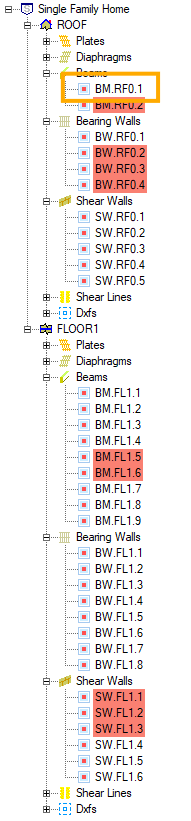
Now BM.RF0.1 is no longer highlighted in red in the navigation sub window. BM.RF0.2 can be updated in the same way.
There may be occasions that default beam type is not the most economical, and we wish to explore an option with a different beam type of beam. For Beam BM.FL1.5, we wish to use glulam beam instead.
Double click the beam (BM.FL1.5) to open the dialog
Go to ‘Sizing’ tab
Select the 2nd Beam Type
Select ‘GLB-Std’, and ‘5.125’ for ‘Width’ at the drop-down menu
Click the Analyze button to run the design on this beam
.png "image(597).png")
Click
.png "image(467).png") to save the edit and close Beam Design Dialog
to save the edit and close Beam Design Dialog
.gif)
Now LAVA stores both options of the beam type, and will print the selected type in the final report.
Review Bearing Wall Design
Double click BW.RF0.3 to open design dialog.
Go to ‘Sizing’ tab. Failure shows in ‘Studs’ tab.
Change ‘Count’ to 2, this will designate double 2×4 studs for this bearing wall.
Click
button to run local analysis. LAVA shows double 2×4 studs are sufficient.Click
.png) to save the change and close the dialog.
to save the change and close the dialog.
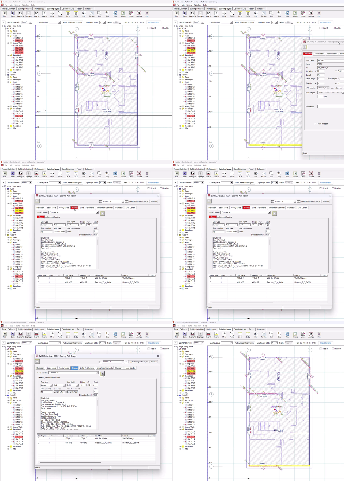
BW.RF0.2 and BW.RF0.4 can be updated in the same way.
Review Shear Wall / Support Post Design
Double click SW.FL1.3 to open design dialog.
Go to ‘Sizing’ tab. Failure shows in ‘Support’ tab.
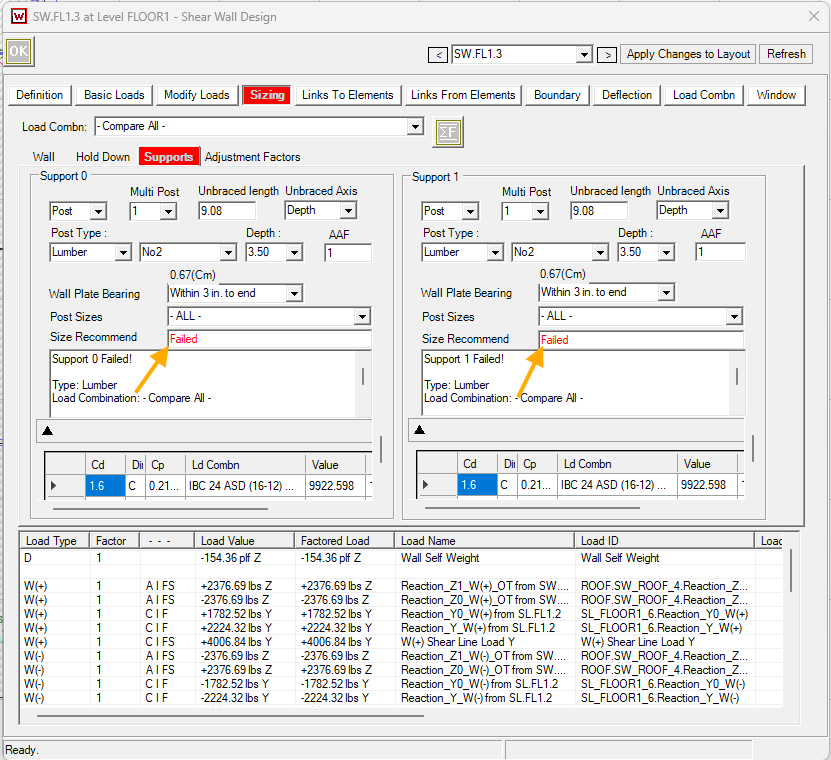
Increase the depth of post to 7.25”, and change ‘Unbraced Axis’ to Width to use 7.25” wide member.
Click
button to run local analysis. Click
.png) to save the change and close the dialog.
to save the change and close the dialog.
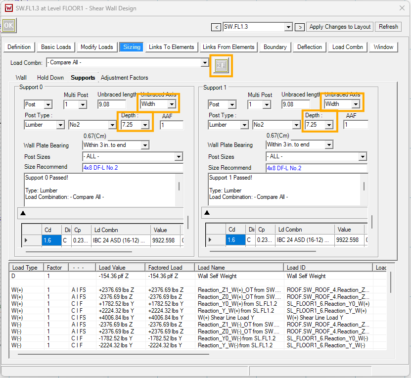
SW.FL1.1, SW.FL1.2, BM.FL1.5, and BM.FL1.6 can all be updated in the same way, increasing support post sizes to 4×6, 4×8, or even 6×6.
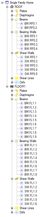
Now all red highlights are cleared, that means all members have passed the capacity check.
Review Shear Wall Hold-Down Design
Before printing the results, it is helpful to review the member sizes and hardware to see if they fit with the actual project. In this case, some shear wall hold-down hardware on FLOOR1 level are light gauge strap such as SW.FL1.1 with CMST14. This is because SW.FL1.1 was copied from ROOF level without further editing. In general, holdown bolts are more applicable in this scenario.
Double click SW.FL1.1 on FLOOR1 level to open the design dialog.
Go to ‘Sizing’ tab and ‘Hold Down’ tab.
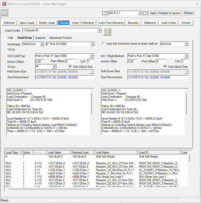
Under Anchorage drop-down menu, select ‘1-Pour 2.5ksi SDC CDEF 0.50G’ to assign holdown bolts in foundation.
Click
button to run a local analysis. Click ‘OK’ to save the change and close the dialog.
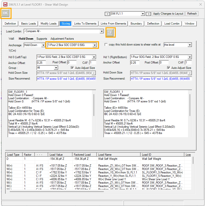
We can do this for every shear wall on FLOOR1 level manually, but if there are too many shear walls that need revising, there is a faster way to change everything at once.
Under ‘Sizing’ and ‘Hold Down’ tab, check the option ‘copy this hold down sizes to shear walls at this level’.
Click
button to run a local analysis. Click ‘OK’ to save the change and close the dialog.
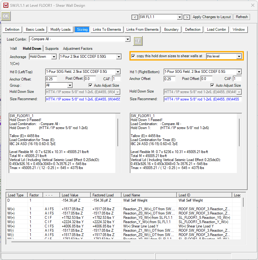
Now all shear wall hold-downs are assigned with HTT4. After the analysis, the hardware on FLOOR1 level is updated.
Click Analyze button on Tool bar to run full structure analysis, so LAVA will check the capacity of HTT4 on all FLOOR1 level shear walls, or select most economical light gauge coiled straps.
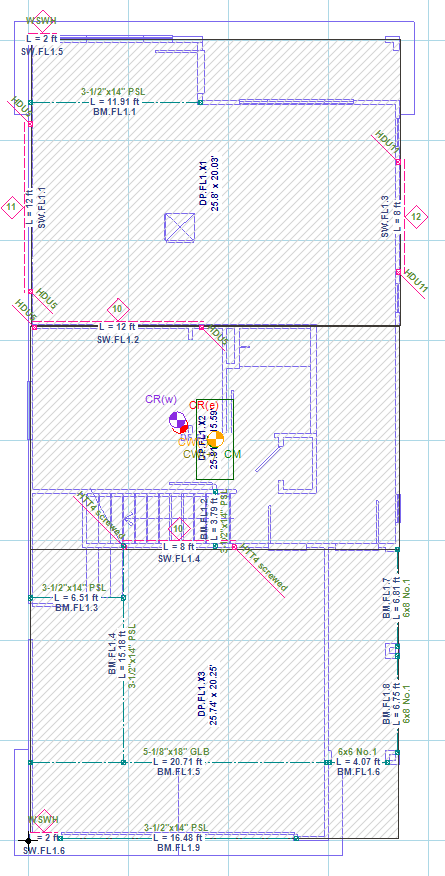
Review Report
To print a report, go to ‘Report’ tab. The navigation sub window shows all available items to be printed. After selection is made, click print review button .png "image(557).png") .
.
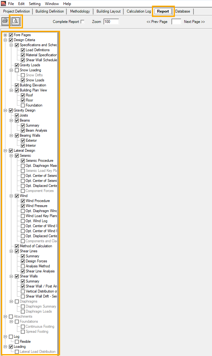
A preview of the final report will be shown on the screen.
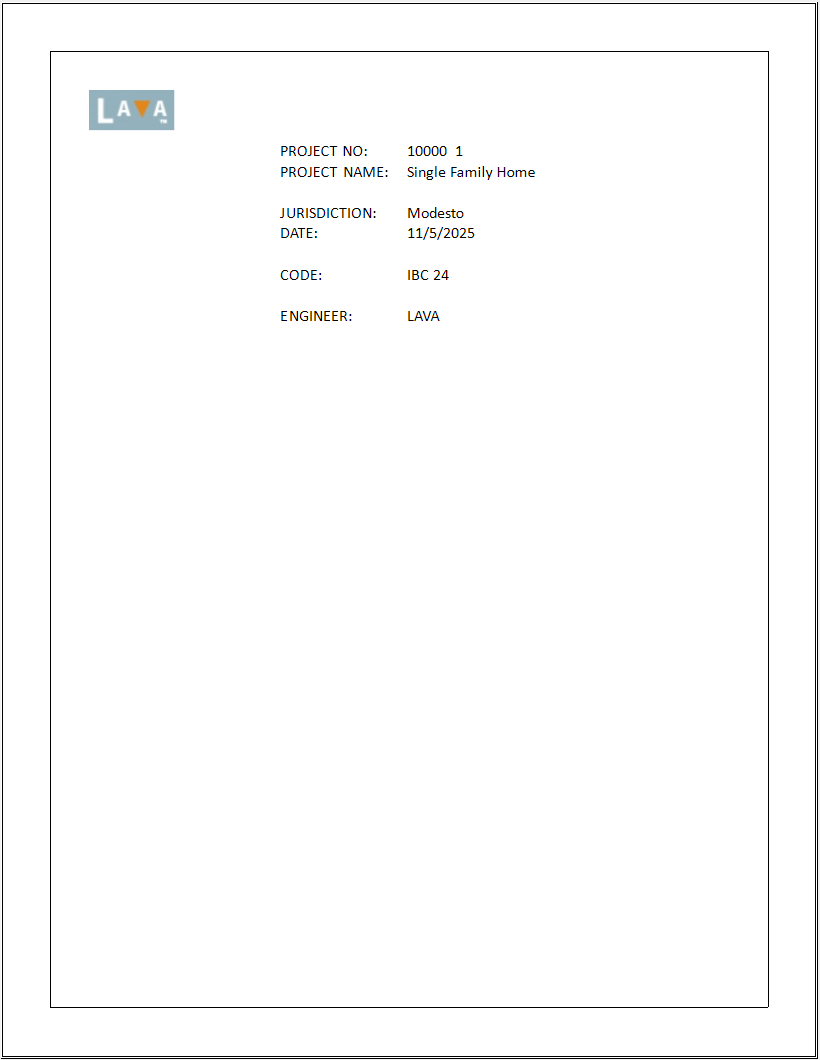
This concludes the entire tutorial.
Download
You can download a sample of this report here.