In this part of tutorial, we will model lateral elements (Diaphragms, Shear Walls, and Shear Lines). Please continue working with the tutorial file that we used in ‘Drawing the Gravity System’ section. Or you can download the file at the end of ‘Drawing the Gravity System’ page and start from there.
Prefer to watch instead? You can also follow along with our step-by-step video tutorials.
Lateral Forces in LAVA
Before we start working with the model, let’s take a moment to learn about how lateral design is addressed in LAVA.
Lateral loads are:
Generated by diaphragm
Collected by shear lines
Distributed to and resisted by shear walls
.png)
There are two directions in the lateral systems in LAVA, X direction and Y direction.
The lateral elements are all associated with either and only one direction.
The two directions (X & Y) are analyzed separately. For example, a diaphragm modeled in X direction has nothing to do with the shear walls or shear lines in Y direction, so to generate and apply lateral loads to shear wall or shear line in Y direction, you must model diaphragms in Y direction..png)
Modeling on ROOF Level
We start the modeling process at ROOF level.
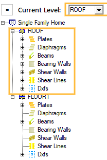
Select ROOF in Current Level, or select any elements under ROOF on the navigation list on the left.
Modeling Diaphragms
LAVA will use the total area of the diaphragm to calculate the seismic weight. In general, diaphragms should cover the entire area.
In X direction, there will be shear lines at exterior walls, and an interior shear line at front of the bedroom suite:
.png "image(499).png")
We will have one diaphragm supported by Shear Line A and B, and another diaphragm supported by Shear Line B and C.
At the top of model space, there is a drop-down menu: .png "image(498).png") . If left blank, model space will display plate elements.
. If left blank, model space will display plate elements.
Select ‘X’ in Diaphragm Lat Dir
.png "image(600).png") , and only diaphragms in X direction will be displayed in model space, and any plate elements or diaphragms in Y direction will disappear.
, and only diaphragms in X direction will be displayed in model space, and any plate elements or diaphragms in Y direction will disappear.Click Diaphragm
.png "image(560).png") on the Toolbar
on the ToolbarDraw a rectangle over the area of diaphragm by clicking the upper left corner and the lower right corner, over Primary Bedroom, Primary Bath, and W.I.C.
Draw the 2nd diaphragm, over the rest of the floor plan.
Press down and hold Shift key on keyboard to activate snap function for accurate modeling
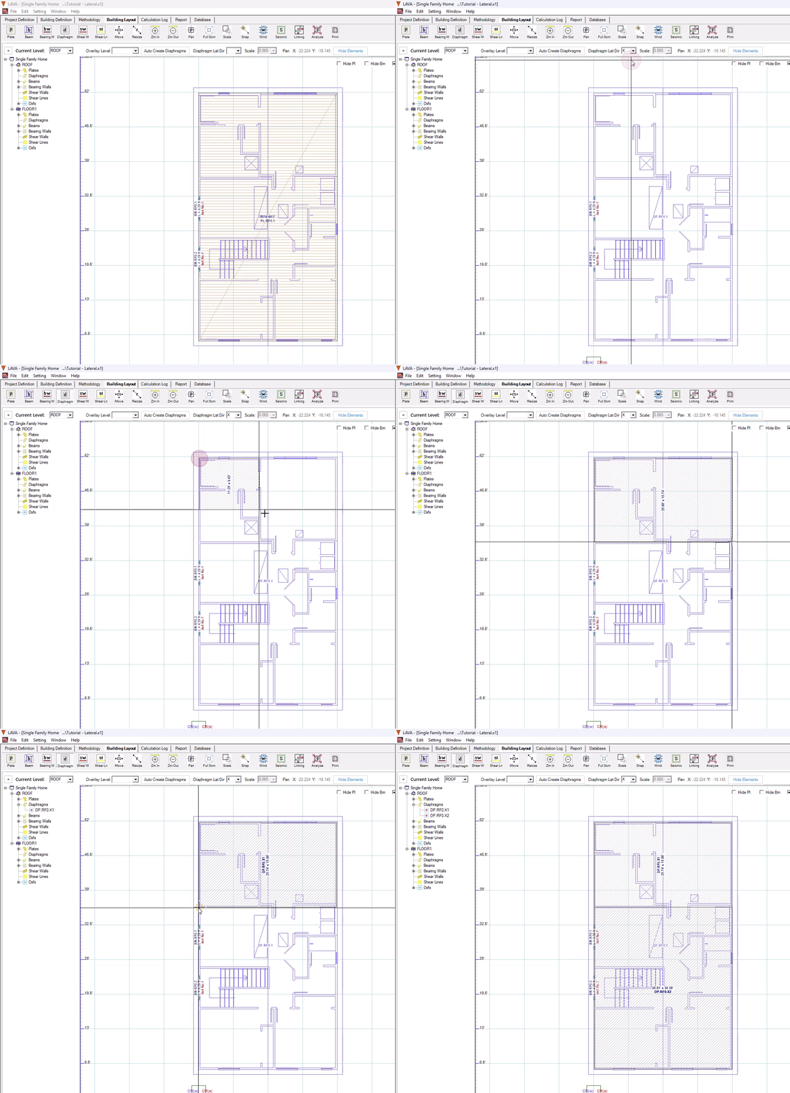
Note that we have only drawn the diaphragms in X direction. We must also draw diaphragm in Y direction to address the lateral loads and resisting elements in Y directions. Since there will be no interior shear wall in Y direction, one large diaphragm will suffice.
Select ‘Y’ in Diaphragm Lat Dir
.png "image(601).png") , and only diaphragms in Y direction will be displayed in model space, and any plate elements or diaphragms in X direction will disappear.
, and only diaphragms in Y direction will be displayed in model space, and any plate elements or diaphragms in X direction will disappear.
Click Diaphragm
on the ToolbarDraw a rectangle over the area of diaphragm by clicking the upper left corner and the lower right corner
.gif)
Modeling and Modifying Shear Walls
Shear walls can be modeled similarly to beams.
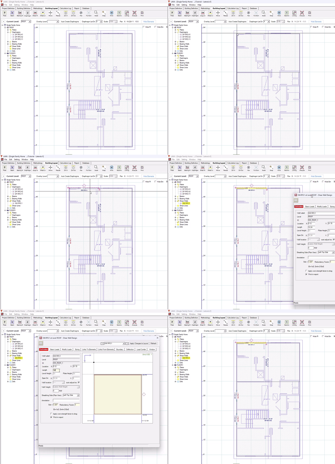
Click ‘Shear W’
.png "image(503).png") on Toolbar
on ToolbarClick and hold the mouse at the starting point of shear wall, and release at the ending point of shear wall
Double click the shear wall to open Shear Wall Design dialog to further edit this shear wall.
Under ‘Definition’ tab, enter length to be 12’
Click ‘Apply Changes to Layout’ to save the change, or click
.png "image(467).png") to save the change and exit the dialog
to save the change and exit the dialog
Force-Transfer-Around-Opening
LAVA can perform analysis of force transferring around openings. For example, there is a window within the shear wall we just modeled in the last step. You can draw the window graphically on the screen by dragging your mouse or you can enter it directly with the location.
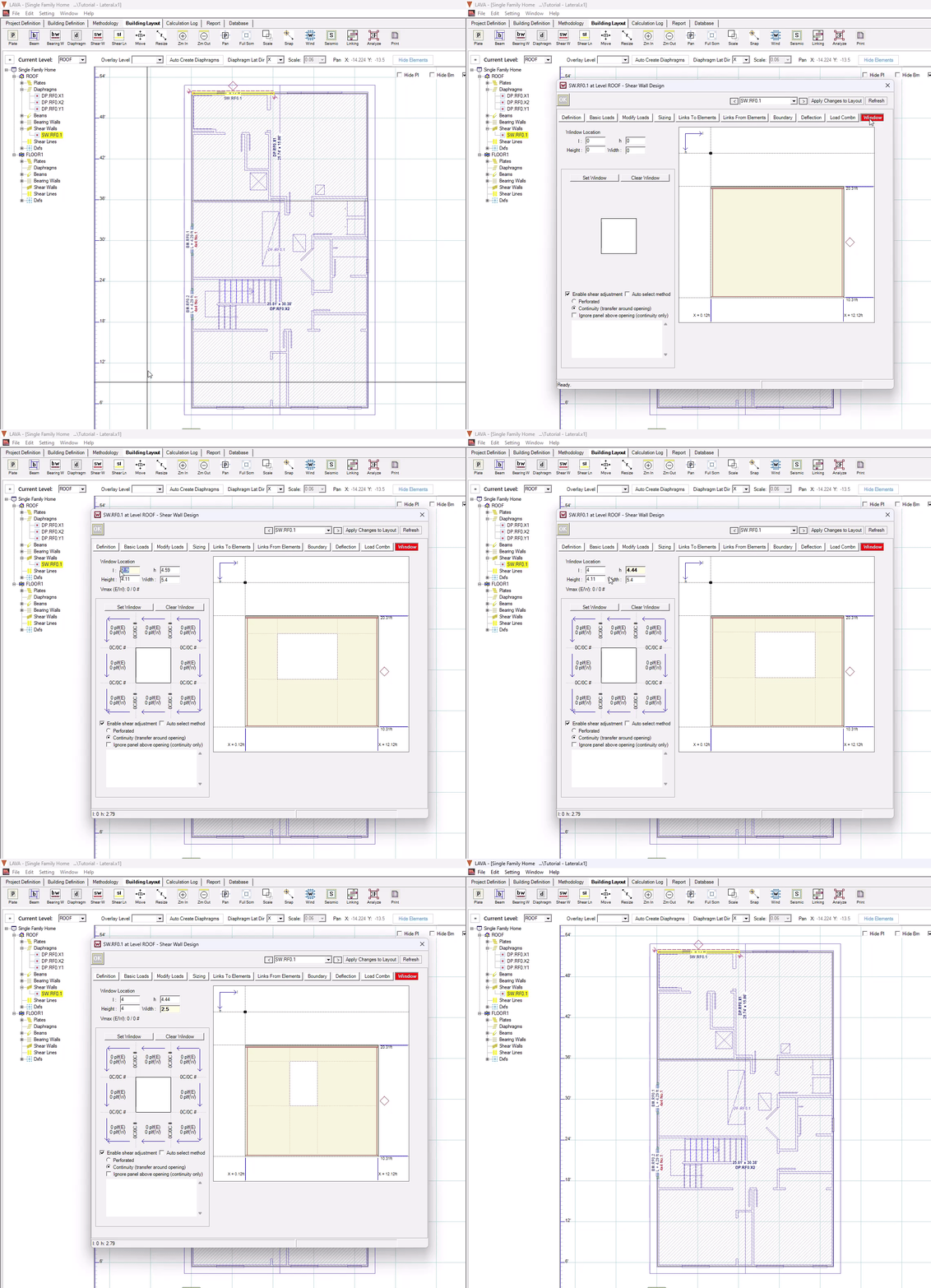
Double-click the shear wall to open Shear Wall Design dialog
Go to ‘Window’ tab
Draw rectangular opening graphically on the wall diagram
Input the dimension of the window opening in ‘Window Location’ section.
l:4’ (Located from the left end of the shear wall)
h: 4.44’ (Height defined in elevation under “Building Definition” tab)
Height: 4’
Width: 2.5’
Click ‘Apply Changes to Layout’ to save the change or click ‘OK’ to save and change and close the dialog.
Copy and Edit Shear Walls at the Same level
When the new shear walls have the same (or similar) geometry or any manually added loads, including the opening defined within the shear wall. The copy-and-paste function can speed up the modeling process. For example, the shear wall in front has the same opening within, we can follow the steps below using ‘copy’ function.
Right-click the shear wall we just modeled (SW.RF0.1) in model space (it should be selected- displayed in yellow)
Select ‘Copy’
Move mouse to the location of the new shear wall
Right-click and select ‘Paste’.
Double-click the new shear wall (SW.RF0.2) to open the dialog. You can see the same opening.
Change the to Sheathing Side: ‘Right/Bottom Side’ for better visual presentation (although this will not affect calculation result)
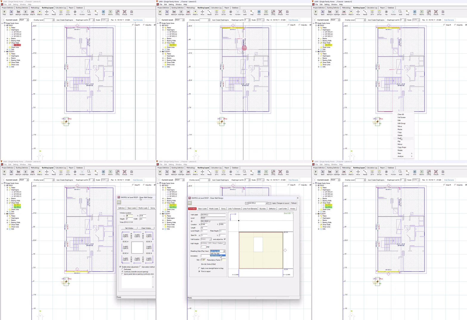
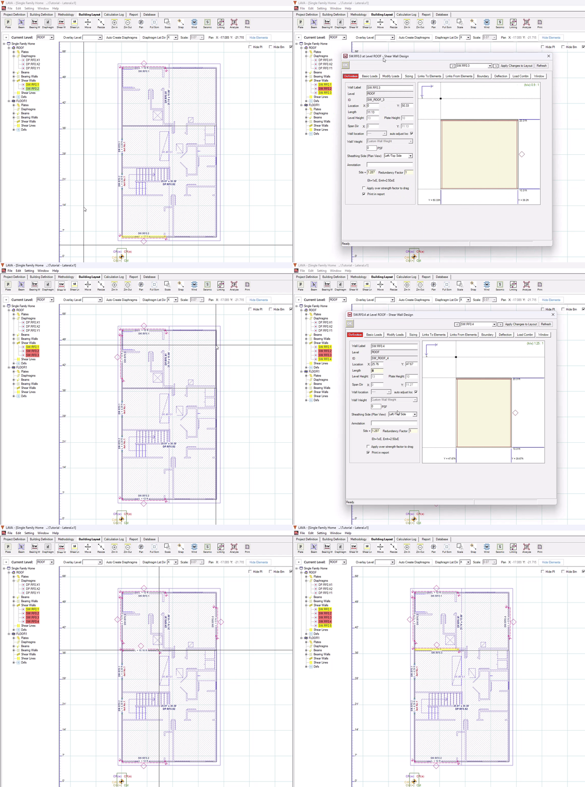
Continue adding shear walls at the left and right side of exterior walls, and the interior shear wall in front of the bedroom suite:
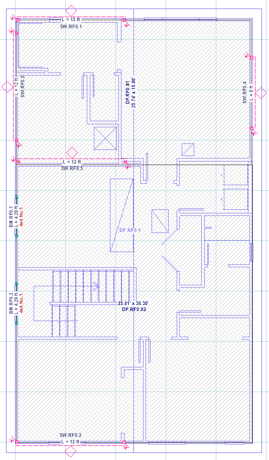
Full Plan View with Shear Walls for your reference:
Modeling Shear Lines
The Shear lines will connect the diaphragm to the shear walls. Please note the order in which these are modeled does not matter.
Click Shear Ln
.png "image(517).png") on Toolbar
on ToolbarDraw rectangle to include the edges of the diaphragms that the shear line will collect loads from, and also to include the shear walls that the shear line will distribute loads to.
Line A is created to include the plan-north edge of the top diaphragm (DP.RF0.X1), and to contain Shear Wall SW.RF0.1
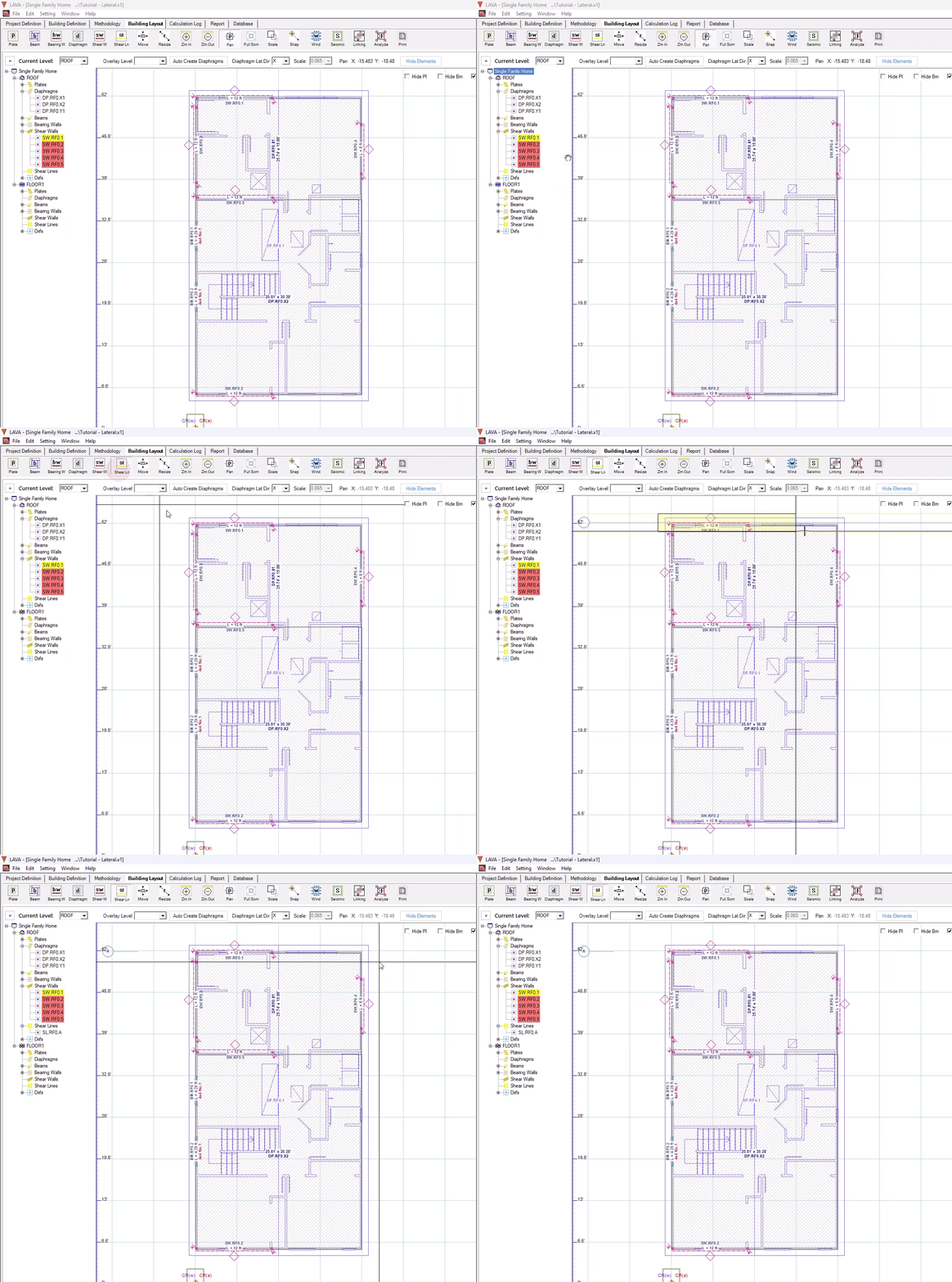
LAVA will automatically snap the shear line to fit the width of the diaphragm:
.png "image(519).png")
Continue drawing the shear lines at the other locations:
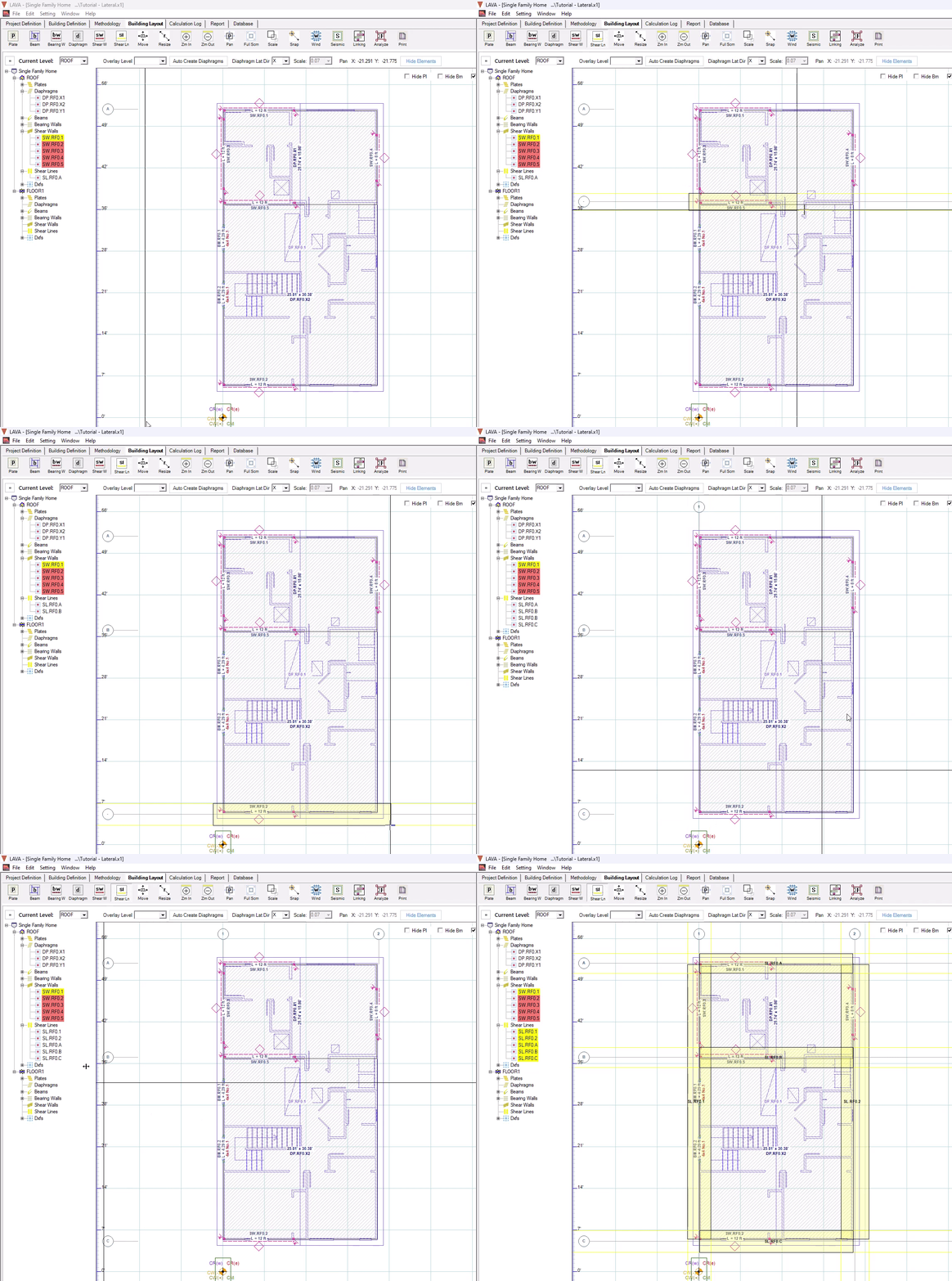
Before we move on, please make sure each diaphragm in X and Y direction has a shear line collecting loads from them on their supports at the edges; and please make sure each shear wall is part of a shear line to receive lateral loads.
Modeling on FLOOR1 Level
If everything looks correct, we move on to FLOOR1 level. Select FLOOR1 in Current Level, or select any elements under FLOOR1 on the navigation list on the left.
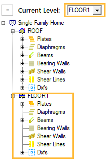
Modeling Diaphragms
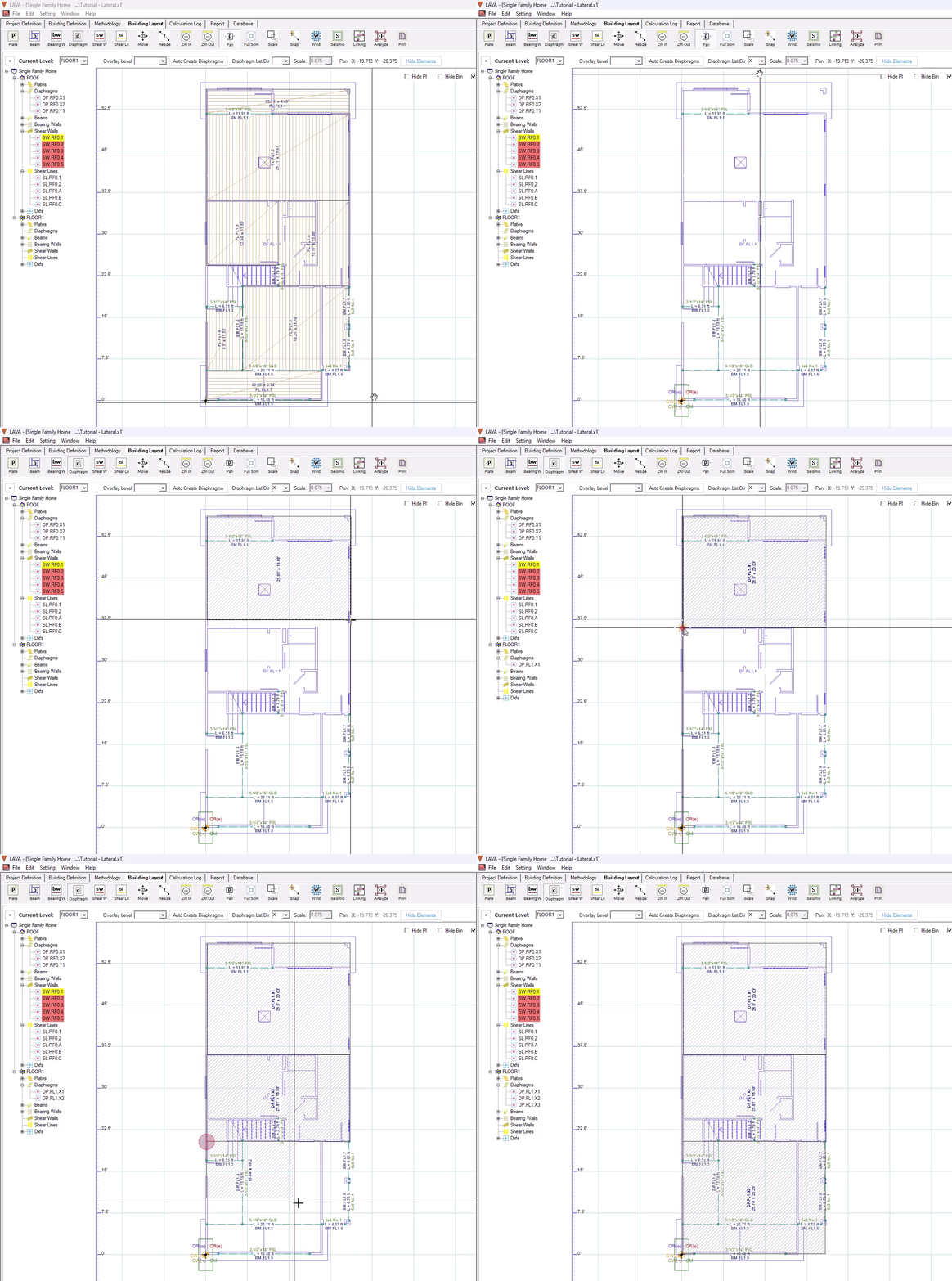
At the top of model space, select ‘X’ in Diaphragm Lat Dir. In X direction on FLOOR1 level, there will be shear lines at exterior walls, an interior shear line at front of the kitchen, and another interior shear line at rear of garage:
.png "image(524).png")
Therefore we will need three diaphragms in X direction. Following the steps below.
Select ‘X’ in Diaphragm Lat Dir
, and only diaphragms in X direction will be displayed in model space, and any plate elements or diaphragms in Y direction will disappear.Click Diaphragm
on the ToolbarDrawing the 1st diaphragm, over Living and Kitchen
Draw the 2nd diaphragm, over Bedroom 4 and Bath 3. Pressure down Shift key on keyboard to activate snap function for accurate modeling
Draw the 3rd diaphragm, over the rest of the floor plan
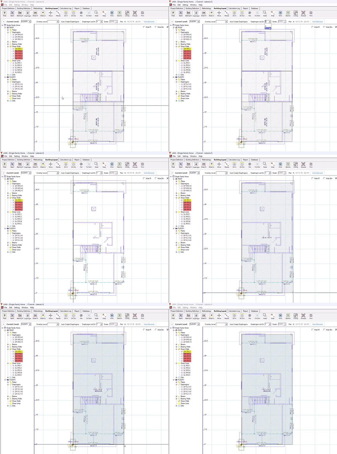
In Y direction, there are only shear walls at exterior walls, therefore only one large diaphragm is needed. Follow the steps below.
Select ‘Y’ in Diaphragm Lat Dir
, and only diaphragms in Y direction will be displayed in model space, and any plate elements or diaphragms in X direction will disappear.
Click Diaphragm
on the ToolbarDrawing a diaphragm over the entire floor plan
Modeling Shear Walls - Copy and Paste between Levels
LAVA can copy and paste elements at the same location between levels. This is especially helpful when shear walls stack between levels. In this two level structure, the exterior shear walls on left and right side, and the interior shear wall in front of the kitchen are stacked with the shear walls on ROOF level. Follow the steps below to copy these shear walls.
Select ROOF in Current Level,
.png) or select any elements under ROOF on the navigation list on the left
or select any elements under ROOF on the navigation list on the leftSelect SW.RF0.3, SW.RF0.4, and SW.RF0.5 by pressing Ctrl key on keyboard and clicking these elements
Go to ‘Edit’ at menu, select ‘Copy’
Select FLOOR1 in Current Level,
.png) or select any elements under FLOOR on the navigation list on the left
or select any elements under FLOOR on the navigation list on the leftGo to ‘Edit’ at menu, select ‘Paste’
We can go to ROOF level, select these three shear walls, and click Edit - Copy (or use Ctrl+C on keyboard):
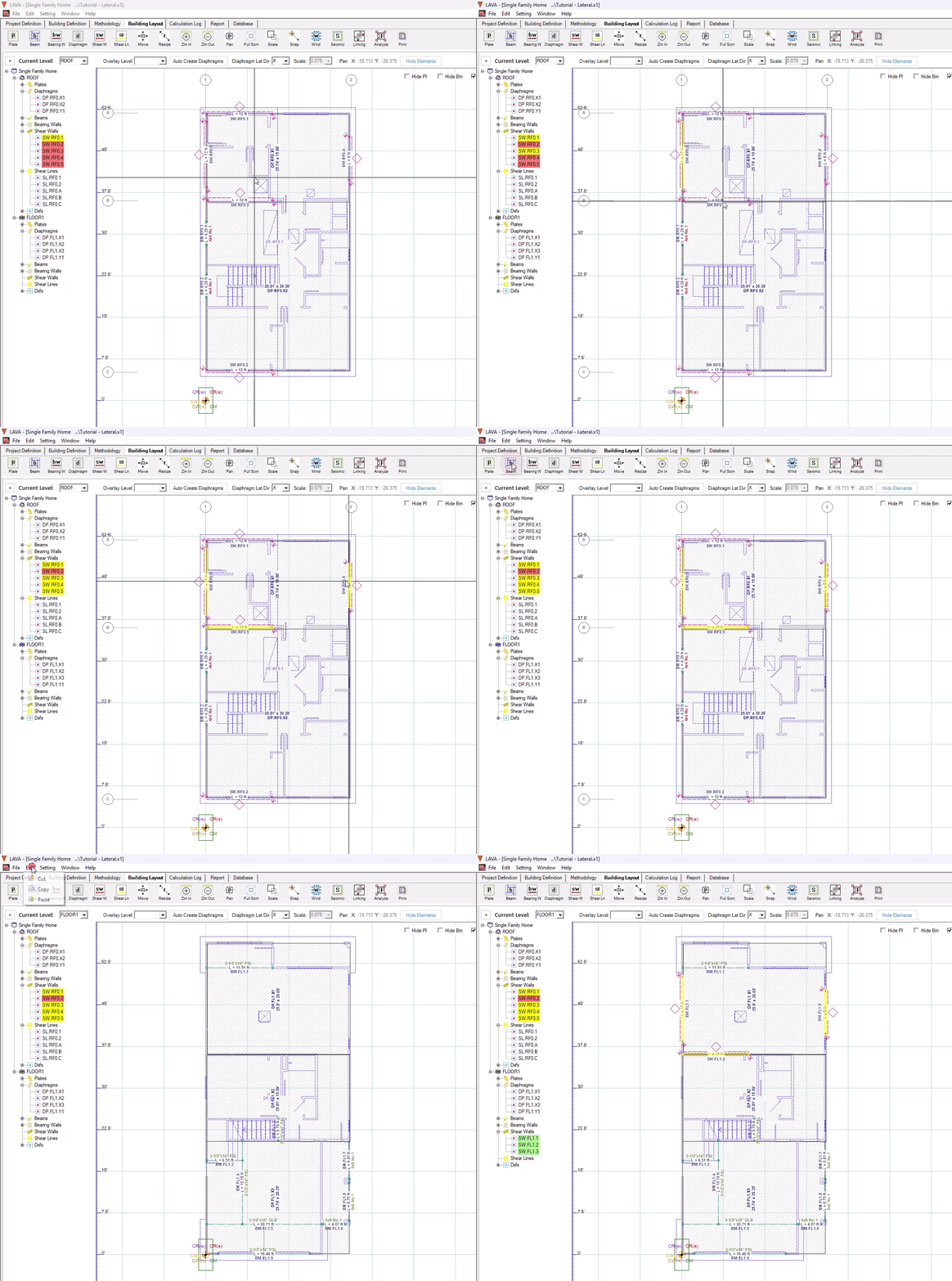
Three new shear walls on FLOOR1 level will be modeled at the same location.
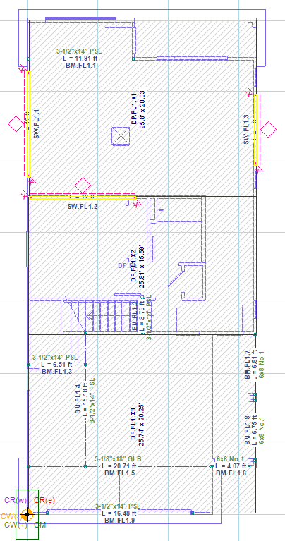
Model an 8’ long shear wall at rear of garage:
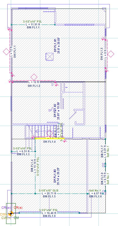
Modeling Shear Walls - Pre-manufactured Panels
At back side of the building, there is not enough space to model a plywood shear wall. We will model a Simpson Strong-Wall panel. Following the steps below.
Model a shear wall on the back of the building:
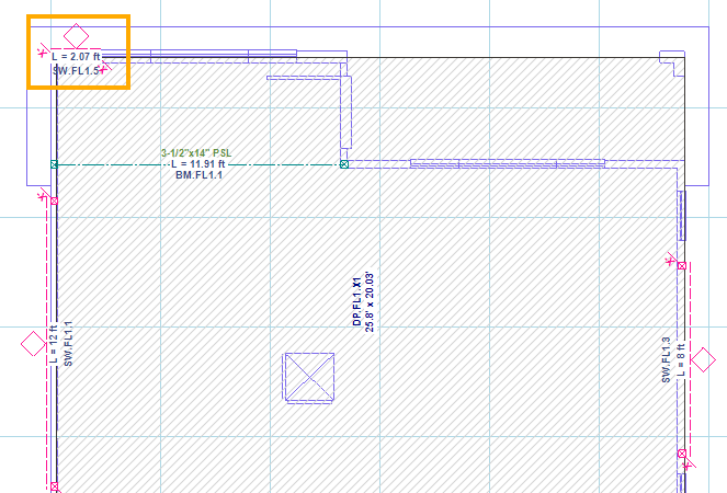
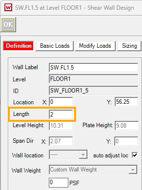
Double click the shear wall to open the Shear Wall Design dialog, and go to ‘Definition’ tab to change the length to 2’.
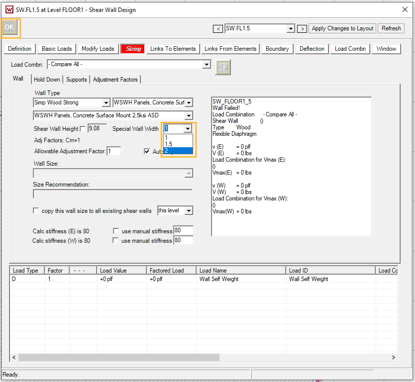
Go to ‘Sizing’ tab. Select ‘Simp Wood Strong’ under ‘Wall Type’:
.png "image(532).png")
Select ‘2’ under ‘Special Wall Width’ to model 24” wide Strong-Wall panel. Click ‘OK’
.png) to save the change and close the dialog.
to save the change and close the dialog.
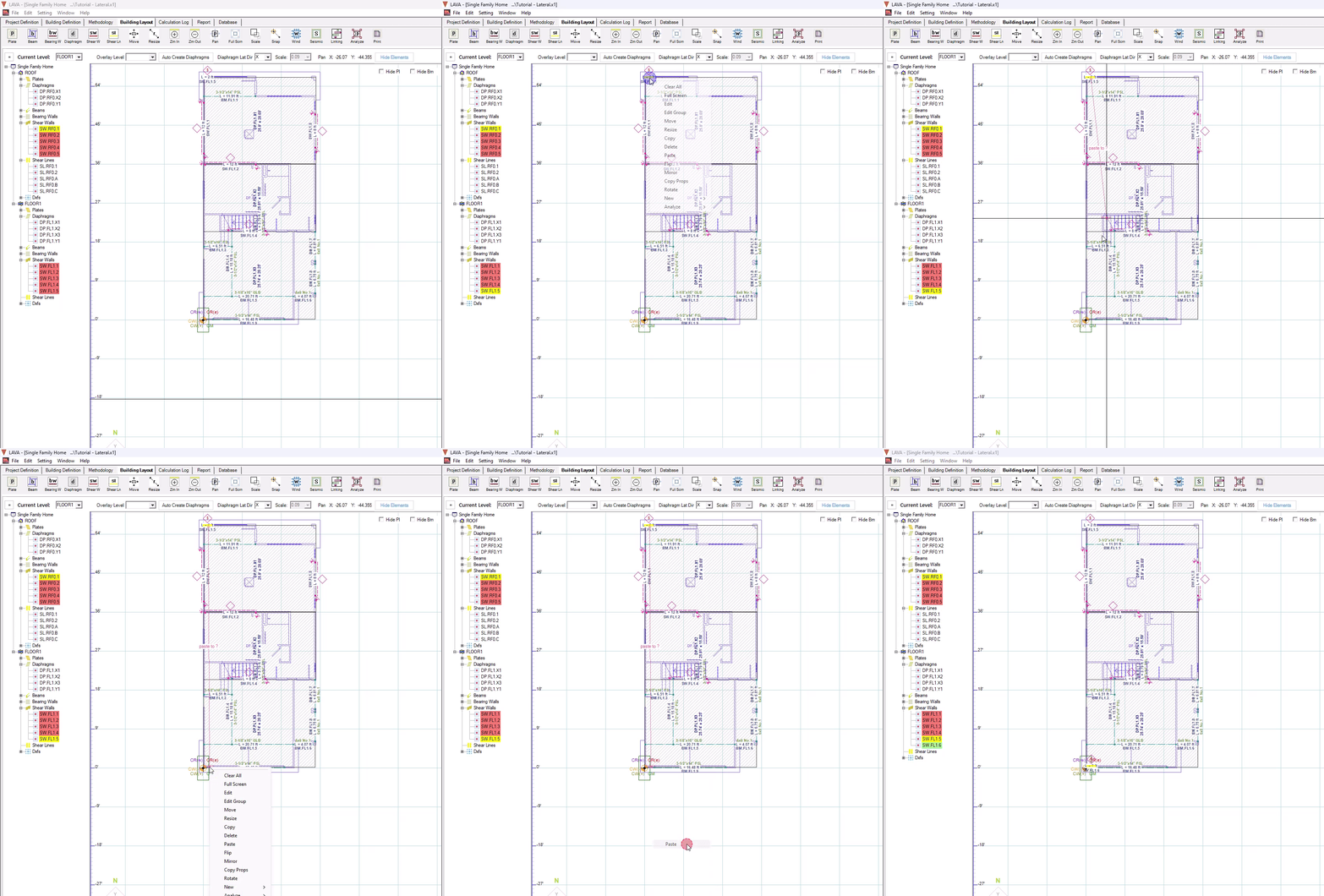
Now a 24” long Simpson Strong-Wall panel is modeled at the back of the building.
Select the Strong-Wall, and right-click, and select ‘Copy’
Move mouse to the location at front of Garage
Right-click and select ‘Paste’
Modeling Shear Lines
Similar to ROOF Level, draw shear lines on FLOOR1 Level. Follow the steps below.
Click Shear Ln
on ToolbarDraw rectangle to include the edges of the diaphragms that the shear line will collect loads from, and also to include the shear walls that the shear line will distribute loads to
Make sure to draw shear lines in both X and Y directions
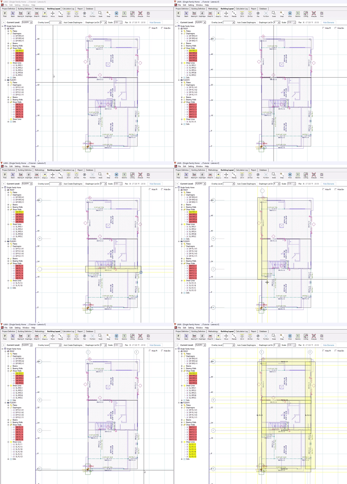
Similar to ROOF level, please make sure each diaphragm in X and Y direction has a shear line collecting loads from them on their supports at the edges; and please make sure each shear wall is part of a shear line to receive lateral loads.
This concludes the lateral system modeling process.