During this part of tutorial, we will model gravity elements (Plates, Beams, and Bearing Walls). Please continue working with the tutorial file that we used in ‘Setting up Parameters’ section. Or you can download the file at the end of ‘Setting up Parameters’ page and start from there.
We will work in the model space in ‘Building Layout’ tab for this step of the tutorial.
Note: Make sure you have already downloaded the DXF file in this first step.
Prefer to watch instead? You can also follow along with our step-by-step video tutorials.
Add DXF Files as Background
The DXF import allows us to trace the building plan view. It’s not required to build a model however it’s very helpful.
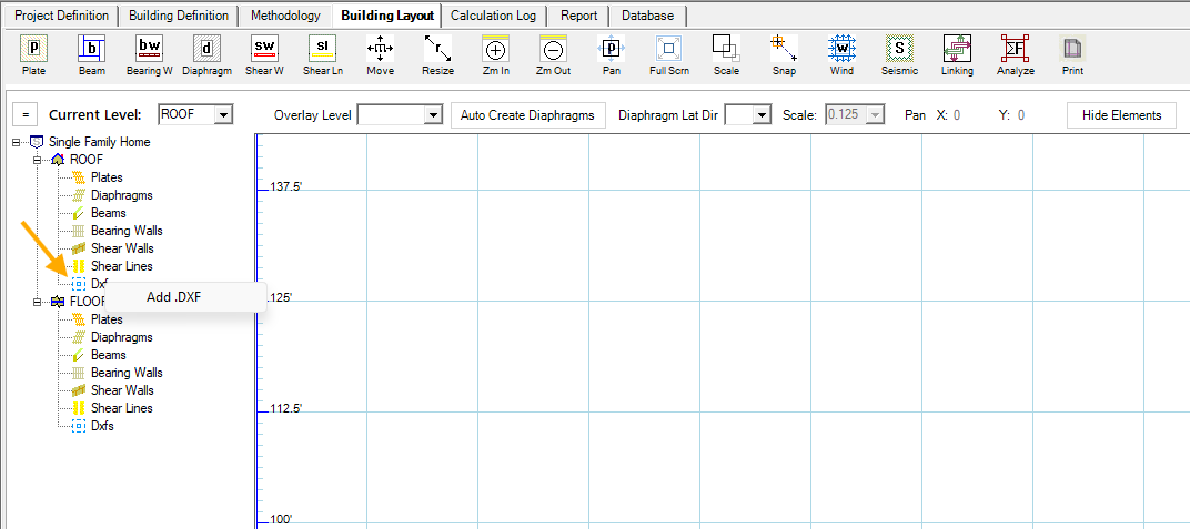
Right click ‘Dxfs’ in the sub window on the left from the ROOF level.
Click ‘Add.DXF’, choose LAVA Tutorial DXF when prompted
Select the layer ROOF to place on ROOF level
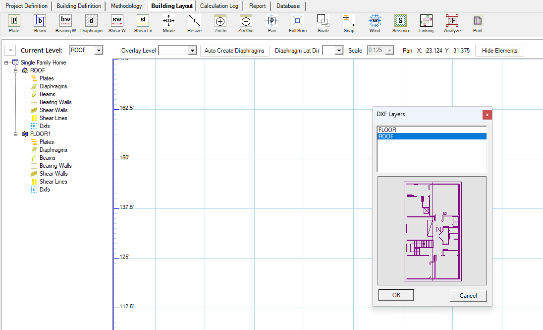
Right click ‘Dxfs’ in the sub window on the left from the FLOOR1 level.
Click ‘Add.DXF’, choose LAVA Tutorial DXF again when prompted
Select the layer FLOOR to place on FLOOR1 level
Now the background DXF files on both levels are imported and should be showing in the background.
Modeling on ROOF Level
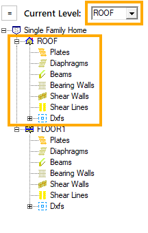
Select ROOF in Current Level, or select any elements under ROOF on the navigation list on the left to navigate to this level.
Modeling Plates
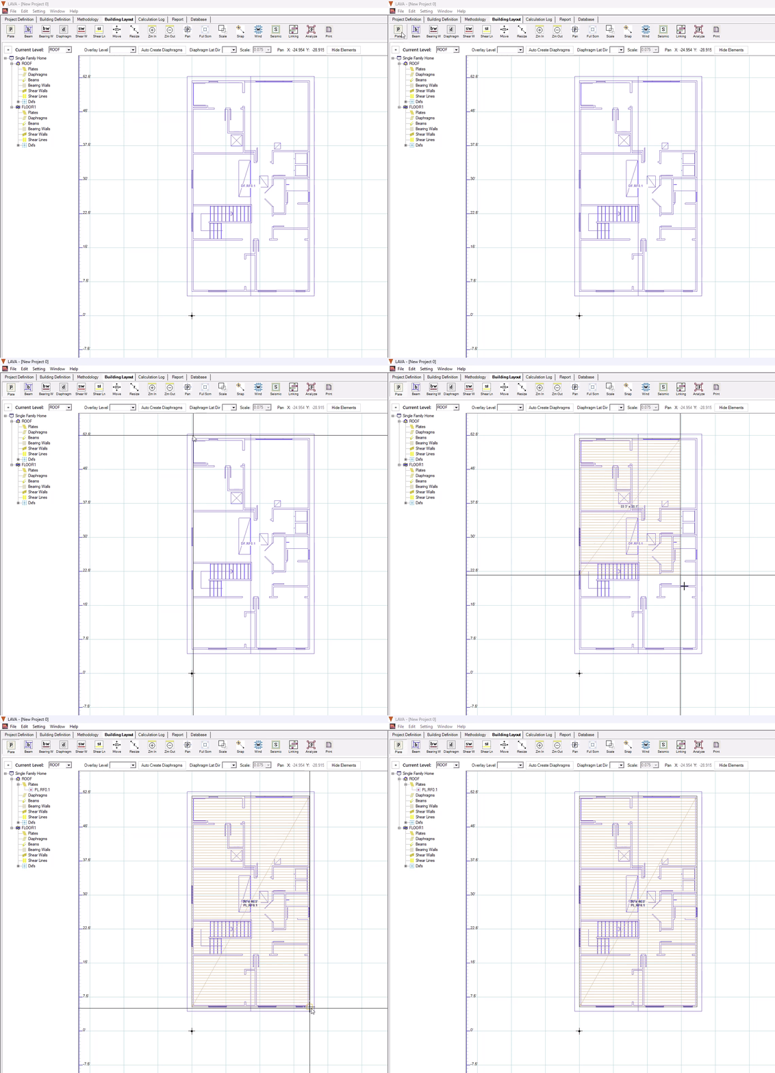
The plates represent the floor or roof level. The orange lines represent the framing span direction. In this case, the roof framing span in X direction.
Click Plate
.png "image(561).png") on Toolbar to activate drawing Plates
on Toolbar to activate drawing Plates Draw a rectangle by clicking the upper left and dragging the cursor and clicking on the lower right corner.
Press and hold the Shift key on keyboard to activate snap for accurate modeling.
Modeling Beams
Beams can be drawn anywhere in your model and the posts are automatically supporting the beams.
Click Beam
.png "image(562).png") on Toolbar to activate drawing the Beam
on Toolbar to activate drawing the Beam Click Shift and click the mouse at the starting point of beam, and drag to the other side and release at the ending point of beam.
Draw the beam 4.29 feet long.
Press and hold the Shift key on keyboard to activate snap for accurate modeling.
If you can’t get exactly 4.29ft, see the section below on Modifications for further help.
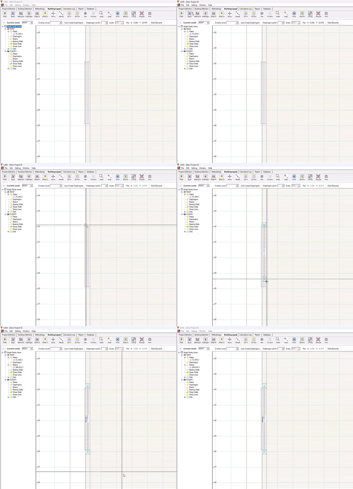
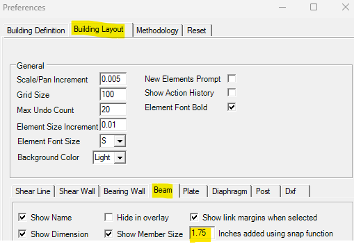
LAVA allows you to Snap to the inner edge of openings and it will automatically offset the edges of the beam by half of the post width. This is a setting that in the Settings- Preferences- Building Layout- Beam that shows the snap function offset by 1.75”.
LAVA automatically adds load from the plate to the beam if the beam is placed within the ‘Link Margin’ of plate (purple shaded stripes when the plate is selected).
To activate the view shown below, just single click on the plate graphically.
.png "image(463).png")
Loads on Beams
The beams will carry the loads from the plates automatically if they are within the purple striped region of the plate.
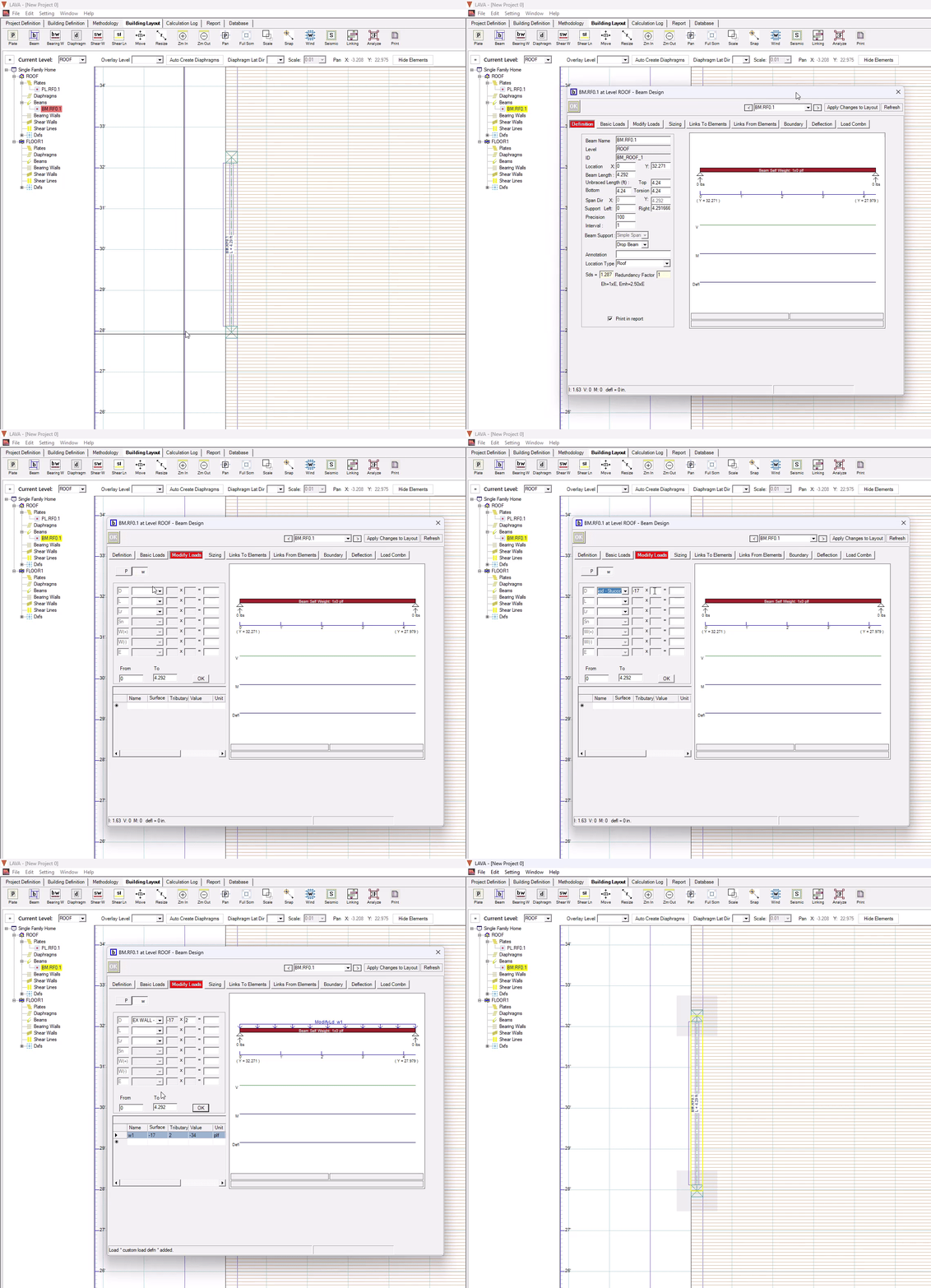
We can add more loads to the beam manually. To manually add additional loads, such as weight of 2’ exterior wall above header, follow the steps below.
Double click the beam to open Beam Design dialog.
Go to ‘Modify Loads’ tab
.png "image(464).png")
Input the following:
Click “w” to apply distributed loads
Select “Ex Wall”
Input 2 for tributary height
Click
.png "image(466).png")
Click
.png "image(467).png") to close Beam Design Dialog
to close Beam Design Dialog
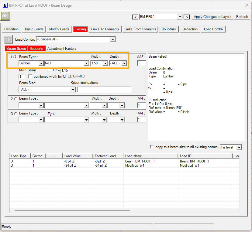
The beam is an exterior header, we typical use sawn lumber. When we run full structural analysis later, LAVA will automatically calculate the most economical size that fits these requirements.
In ‘Sizing’ tab, we input the following:
Select ‘Lumber’ and ‘No1’ for Beam Type
Input 3.5” for Width.
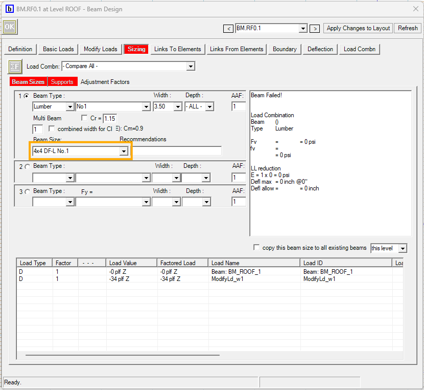
If there is a specific size you would like to use, for example 4×4 header, you can assign that size directly and LAVA will check the capacity when we run full structural analysis later.
Select the Beam Size: 4×4 DF-L No.1
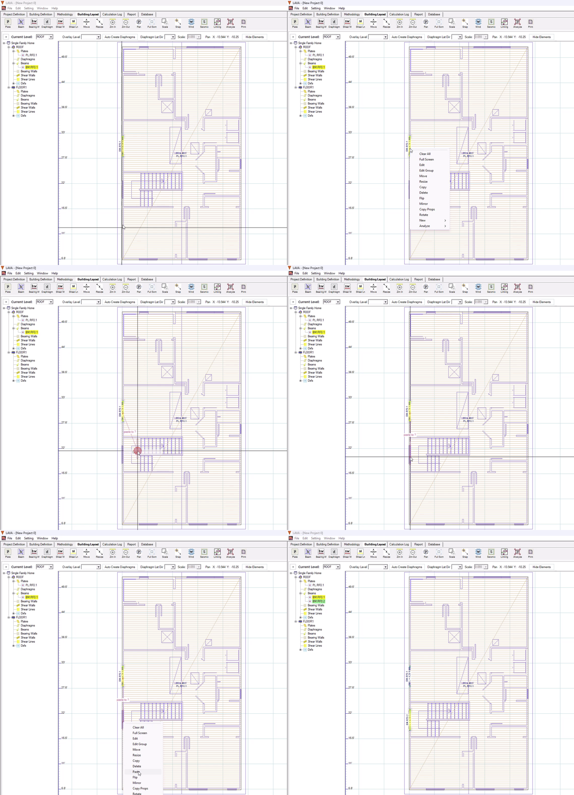
Let’s continue to draw more Beams in the exterior wall. The new beam will have the same geometry (length, unbraced length, cantilever), beam type or size, and manually added loads with the original beam.
Right click the beam we just modeled (BM.RF0.1) in model space
Select “Copy”
Move mouse to the location of the new beam
Right click and select “Paste”
Modifications
If you can’t get your element the right size or placement, there’s a few great quick modification tools.
Resize
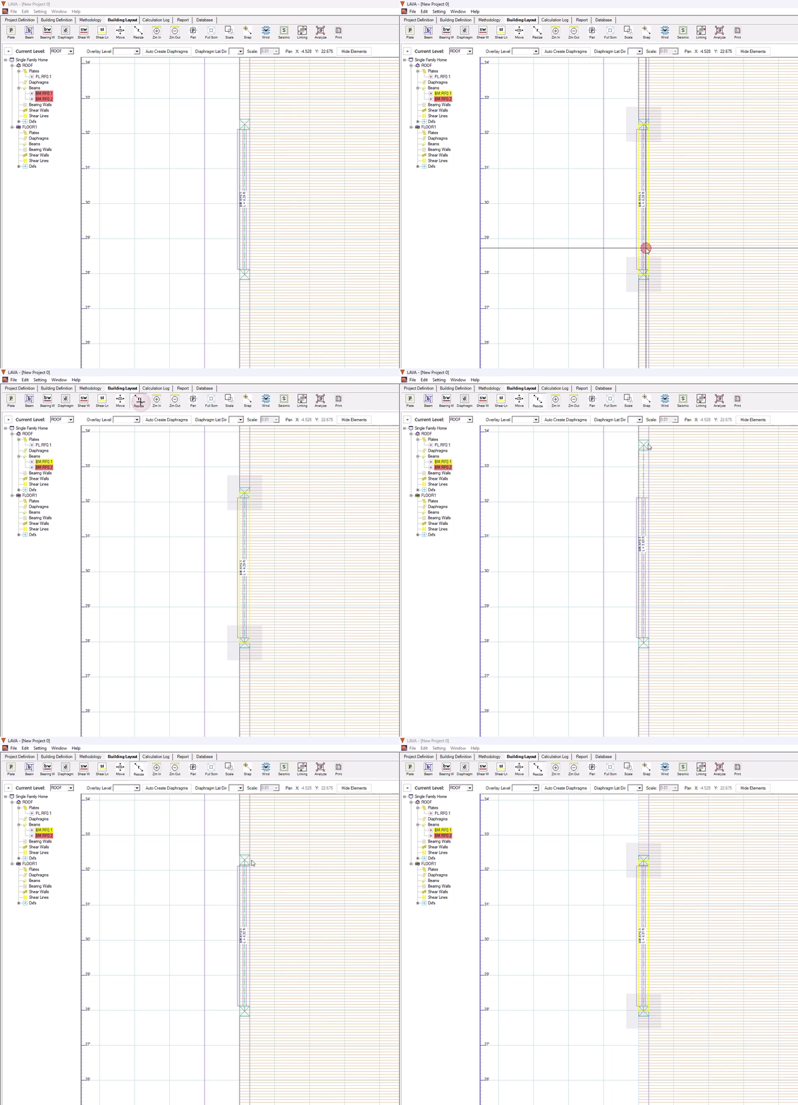
This allows you to graphically Resize the beam. Note this tool also works on walls.
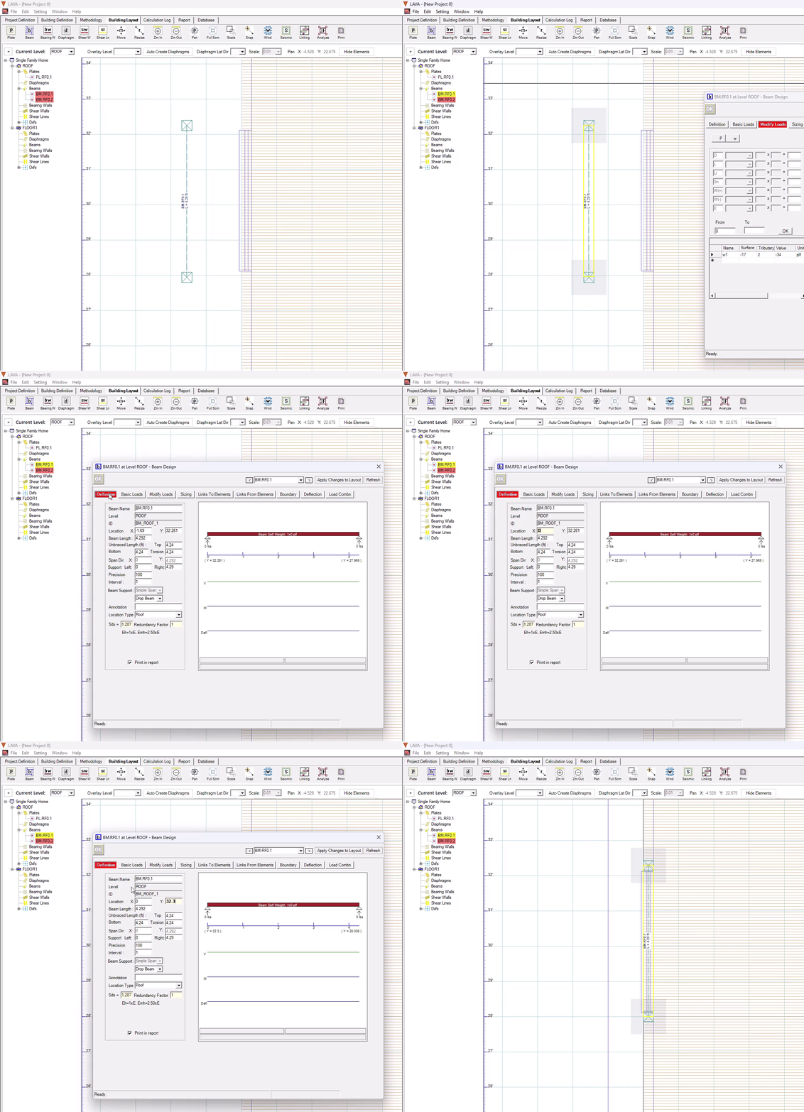
Select the beam (it turns yellow)
Click Resize icon
Note: you can also click and hold “r” on your keyboard as a shortcut
Click, hold and drag on the post to resize the beam to the desired length
Move
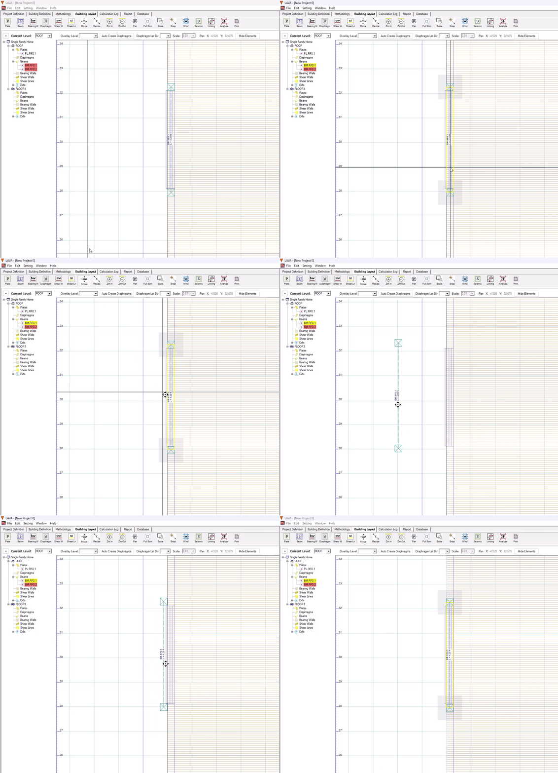
This allows you to graphically Move the beam. Note this tool also works on walls.
Select the beam (it turns yellow)
Click Move icon
Note: you can also click and hold “m” on your keyboard as a shortcut
Click, hold and drag on the post to move the entire beam to a new location
Edit Location Manually
If the graphical input is not working for you, you can always edit the beam in the dialog.
Double click the beam to open the dialog
Set the X & Y location to define the origin
Set the Beam Length directly
Modeling Bearing Walls
Bearing walls carry loads vertically down the building for gravity loads.
Note: You do not need to draw bearing walls under plate, the vertical loads will transfer vertically to the next level. You can also take the approach of checking a section of the bearing wall rather than drawing all the bearing walls in the floor level.
For the structure in this tutorial, we can see the exterior walls do not align between upper and lower levels at plan-north and plan-south. By modeling bearing walls at these locations on ROOF level, LAVA can automatically add the self-weight of bearing walls to the elements below. If we do not model these bearing walls on ROOF level, we must manually add the self-weight of these walls to the beams below.
Bearing Walls can be modeled graphically the same way as Beams, follow the steps below.
Click ‘Bearing W’
.png "image(563).png") on Toolbar
on ToolbarClick the mouse at the starting point of wall, and release at the ending point of wall.
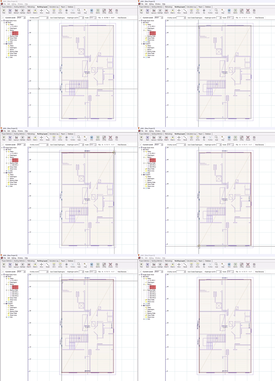
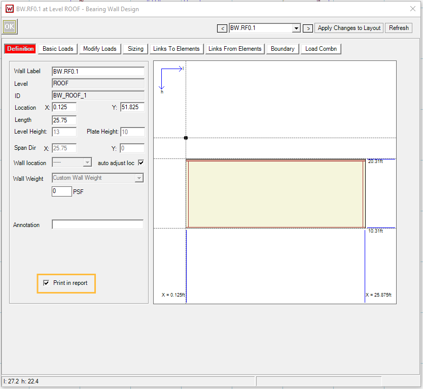
By default, LAVA does not include bearing wall calculation in the final report due to the redundancy of these calculations would increase the size of the report. We will include a few of these walls for our report.
Double-click the bearing wall BW.RF0.1 to open Bearing Wall Design dialog
Go to ‘Definition’ tab
Check ‘Print in report’
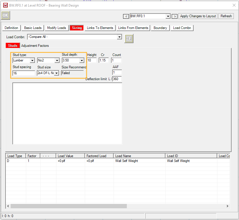
In ‘Sizing’ tab, we see default size and spacing requirements in LAVA. You can also assign a specific stud size or spacing, and LAVA will check the capacity when we run full structural analysis later.
Assign the Stud Size: 2×4 DFL
Set Stud Spacing: 16” on center.
Let’s run the analysis for this wall to check this design.
Click the Analyze button to run the design on this wall
.png "image(597).png")
Click ‘Apply Changes to Layout’
.png "image(598).png")
Navigate to the other Bearing walls using the arrows at the top of the dialog
Assign the Stud Size: 2×4 DFL
Click ‘Apply Changes to Layout’
Continue to the next Bearing walls and repeat
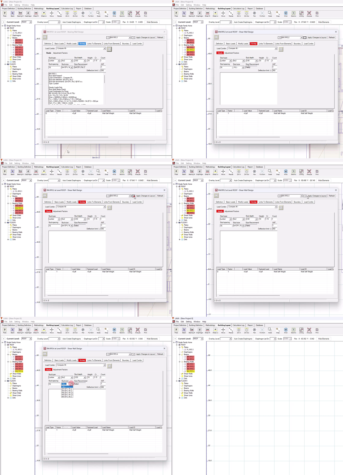
Congratulations! Roof Level is complete.
Modeling on FLOOR1 Level
Modeling Plates
We move on to FLOOR1 level.
Select FLOOR1 in Current Level or select any elements under FLOOR1 on the navigation list on the left.
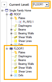
Let’s draw Plates on the Floor1. These plates represent the floor level.
Click Plate
on Toolbar to activate drawing Plates Draw a rectangle by clicking the upper left and dragging the cursor and clicking on the lower right corner.
Press and hold the Shift key on keyboard to activate snap for accurate modeling.
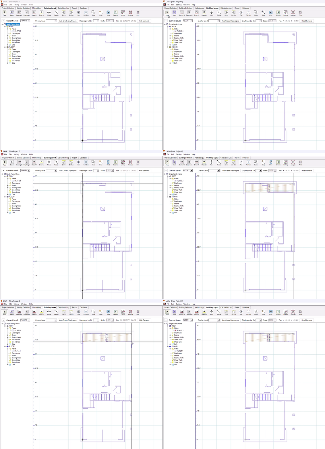
Modeling a Low Roof
The plates model at levels other than ROOF are automatically assigned with default Floor load assembly and are considered flat. If certain plates are to be designed with loads other than default floor load, such as a lower roof, you can adjust them directly.
Double click on the Plate
Go to ‘Definition’ tab
Change Location Type to Roof
Input roof slope: 4/12
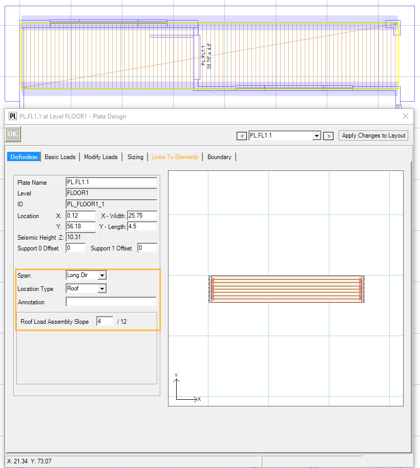
Go to ‘Basic Loads’ tab,
Review the Load Assemblies is updated with default roof load.
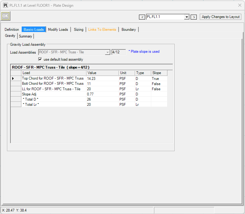
For more complicated projects, where you will define flat roof, or in-unit balcony with 60psf live load, or common corridor with 100psf live load, you can use the method above to model plates with accurate loads.
Modeling Beams - Using Overlay Background
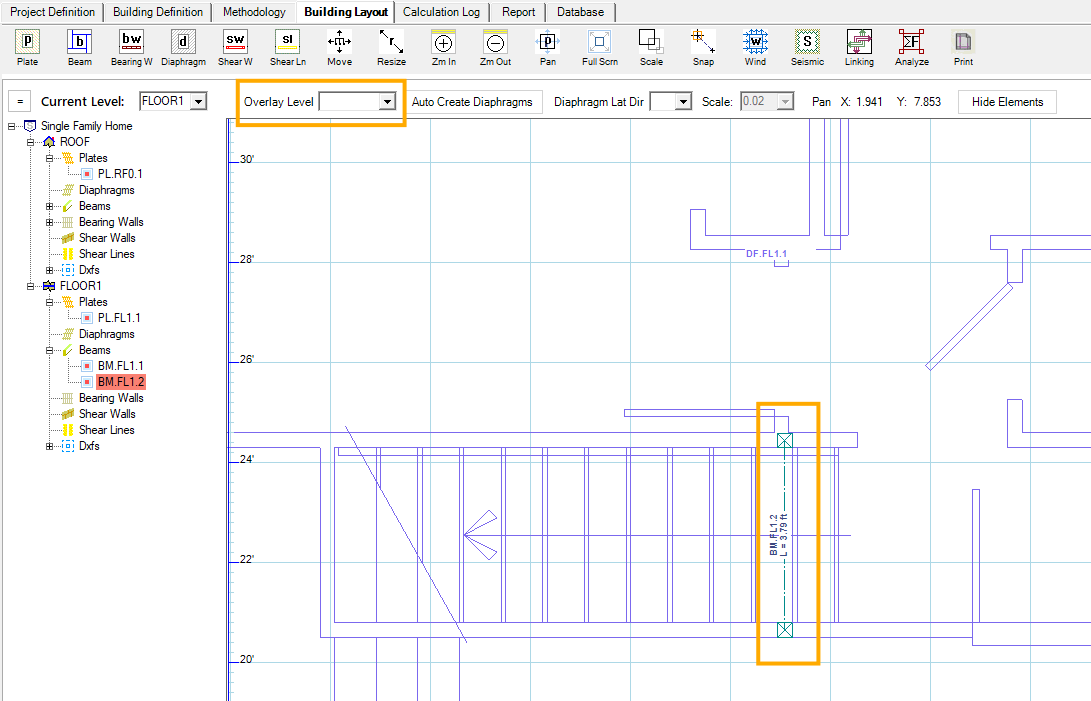
The beams can be added in a similar way as in ROOF level. Sometimes, a beam at lower level must be placed to catch loads from elements in the upper level, or to accurately reflect specific framing conditions such as stair well. It is helpful to use ‘Overlay Level’ function to overlay upper level (or lower level sometimes) so the beams can be placed at accurate locations.

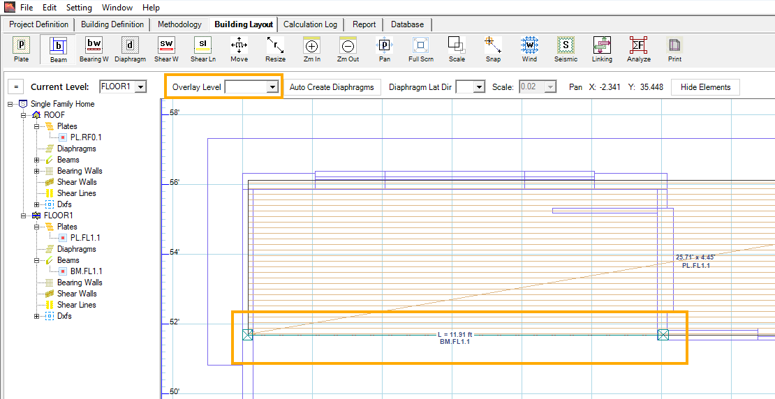
Condition 1: We must model a load bearing beam to support the exterior wall from the upper level.
Select ‘ROOF’ for overlay level, and roof level background will show up in model space with green lines.
Click Beam icon
Draw a Beam at the same location of exterior bearing wall at ROOF level.
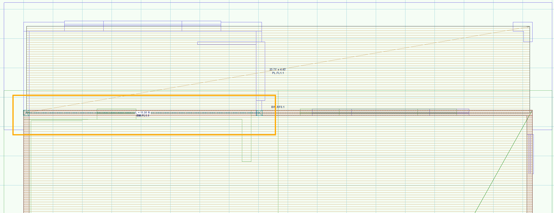
Turn off the overlay level
Use ‘Move’ and ‘Resize’ tools to make adjustments as needed.
Condition 2: We must model a beam at the edge of stair well on FLOOR1 level, but the stair well walls are shown on the background on ROOF level.
Select ‘ROOF’ for overlay level, and roof level background will show up in model space with green lines.
Click Beam icon
Draw a Beam at the same location of stair well wall at ROOF level.
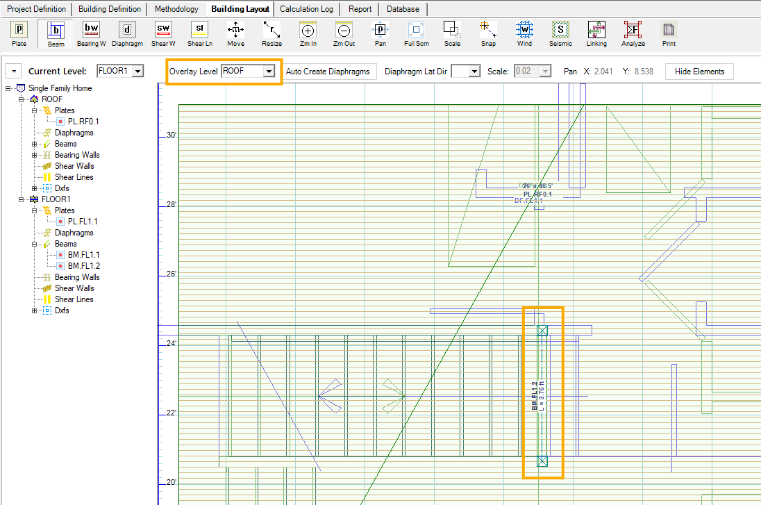
Turn off the overlay level, and use ‘MOVE’ and ‘RESIZE’ tools to make adjustments as needed.
Modeling Plates and Beams - Finishing the FLOOR1 Level Framing
The rest of the gravity elements can be modeled in the same way. Let’s continue with the Plates.
Click the Plates icon
Draw the next three framing areas as shown below
The orange lines represent the framing span direction. In this case, the roof framing span in X direction.
Double-click the plate to open the dialog
Set the Span: Long Direction
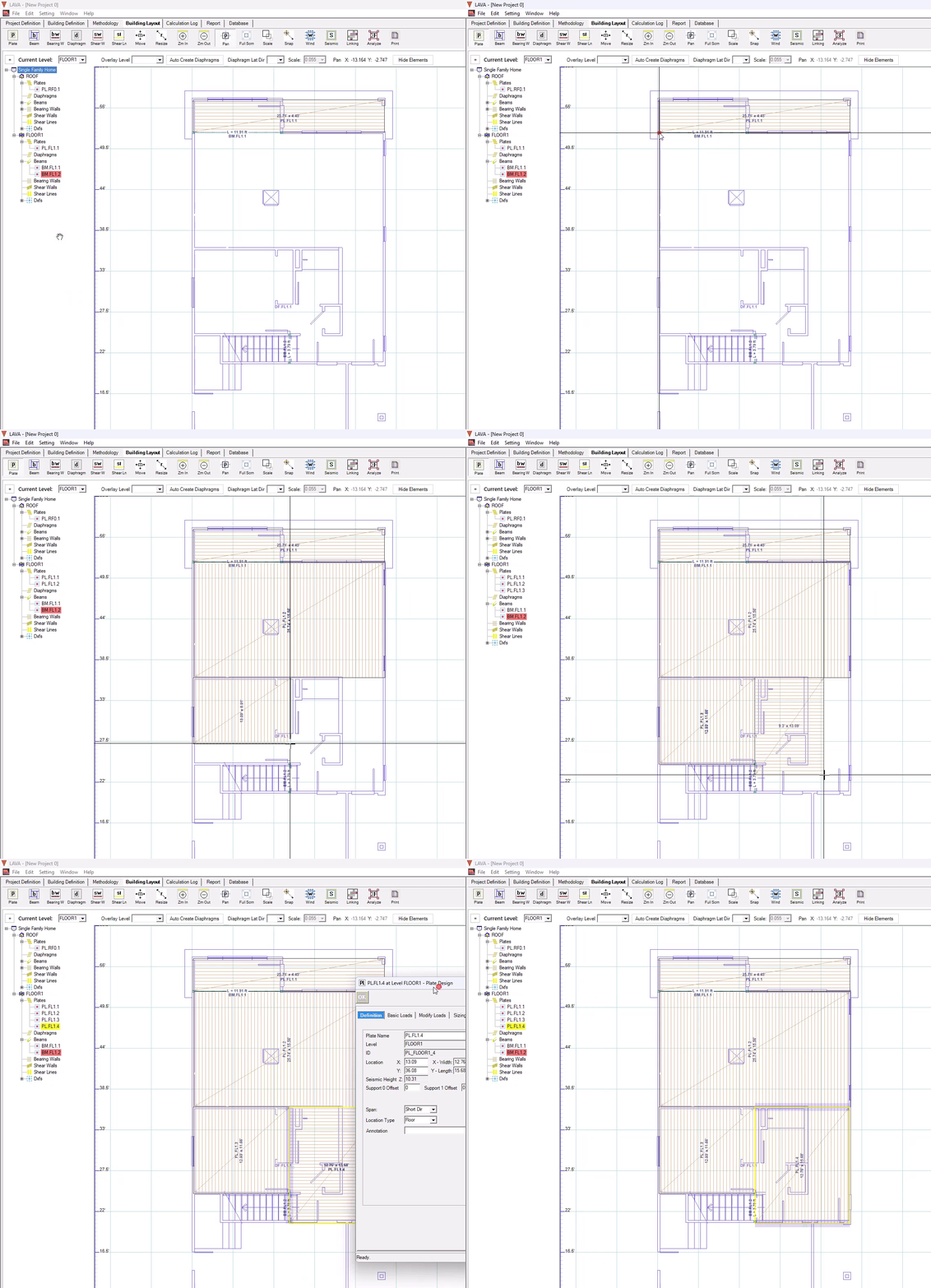
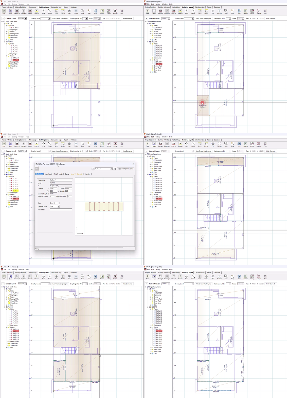
Finish modeling the floor and lower roof plates, headers and interior beams as well.
Click the Plates icon
Draw the next three framing areas as shown below
Adjust the Framing direction by double-click the plate to open the dialog
Set the Span: Long Direction
Click the Beam icon
Draw in the supporting beams as shown
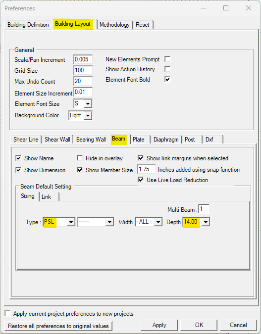
Note: In this tutorial, we assign 4x or 6x DFL members for headers, and assign 14” deep LSL or PSL members for interior beams. These beams sizes are defaulted in the Settings- Preferences- Building Layout- Beams tab.
Edit Beam Type Manually
There may be occasions that default beam type is not the most economical, and we wish to explore an option with a different beam type of beam. For Beam BM.FL1.3, we wish to use glulam beam instead.
Double click the beam (BM.FL1.5) to open the dialog
Go to ‘Sizing’ tab
Select the 2nd Beam Type
Select ‘GLB-Std’, and ‘5.125’ for ‘Width’ at the drop-down menu
Click
to save the edit and close Beam Design Dialog
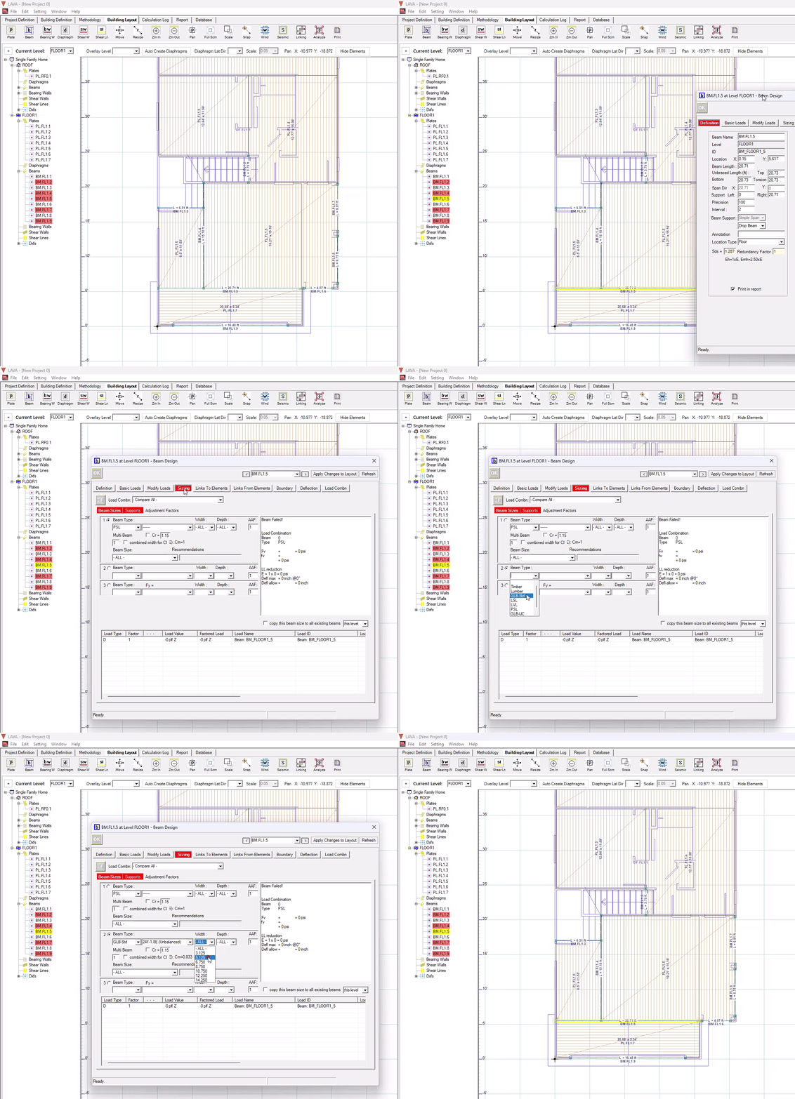
Now LAVA stores both options of the beam type, and will print the selected type in the final report.
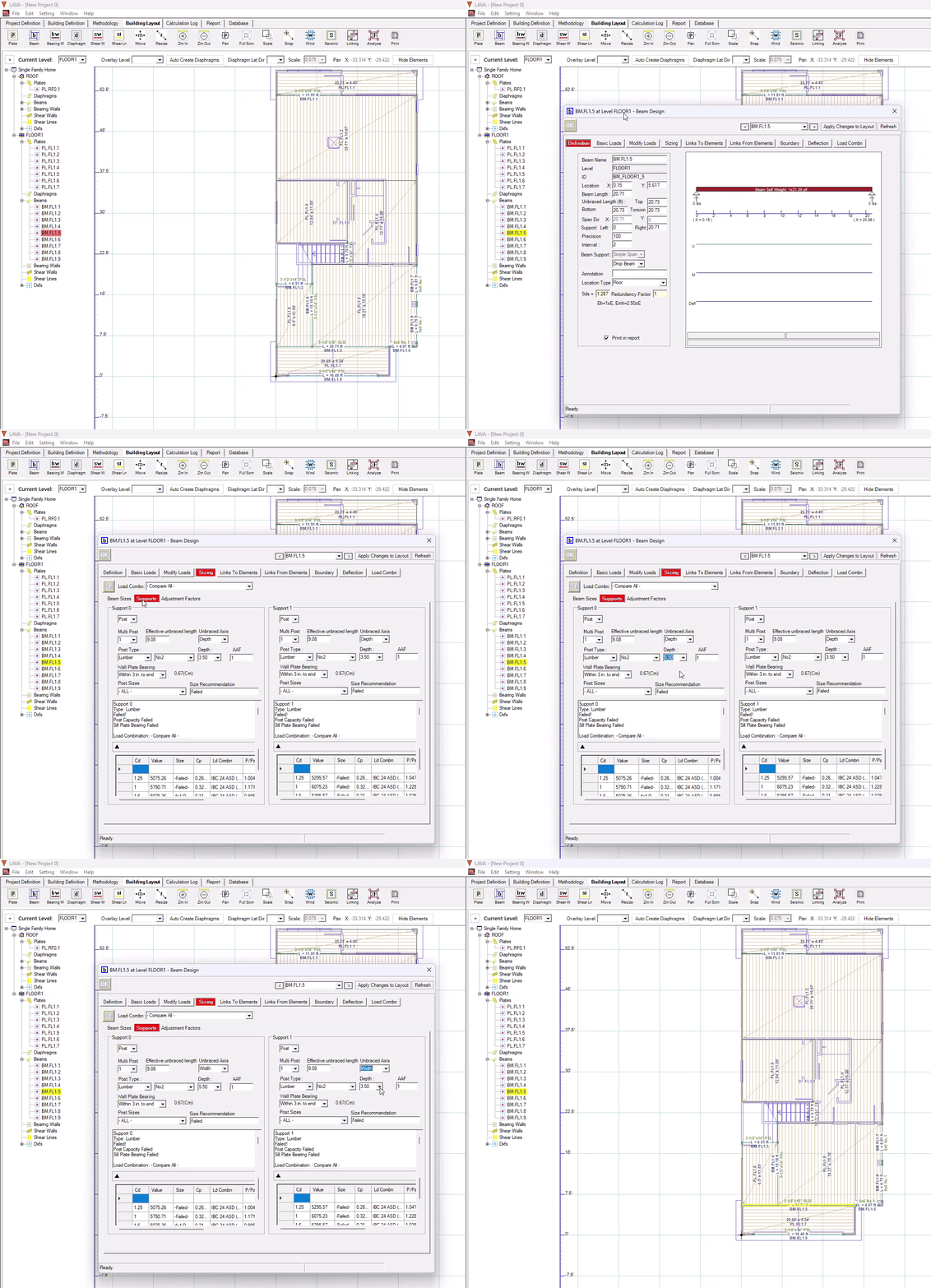
Edit Beam Support
LAVA calculates supporting posts for beam. If the supports fail, the member ID on the navigation list will be displayed in red. We can edit the supporting posts accordingly.
Double click the beam (BM.FL1.5) to open the dialog
Go to ‘Sizing’ tab, and ‘Supports’ sub tab
Note that Support 0 and 1 fail
Select ‘5.50’ for ‘Depth’ at the drop-down menu
Select ‘Width’ for Unbraced Axis, since drywall will be present in the ‘Depth’ direction and provide bracing
Click the Analyze button to run the design on this beam
Click
to save the edit and close Beam Design Dialog
Modeling Bearing Walls on FLOOR1 Level
LAVA can export reaction forces (point loads and line loads) to a .txt file, which is also easily compatible with Microsoft Excel. This is very helpful to deliver reaction forces to podium designing team. However, to produce a complete and accurate export, it is advised that all plates are enclosed with bearing walls and / or beams. If you are not exporting reactions for your project, please skip this step and the next one.
Click ‘Bearing W’
on ToolbarClick and hold the mouse at the starting point of wall, and release at the ending point of wall
Observe and navigate all plates to ensure they are enclosed by bearing walls and / or beams
Click ‘Analyze’
.png) on Toolbar
on Toolbar
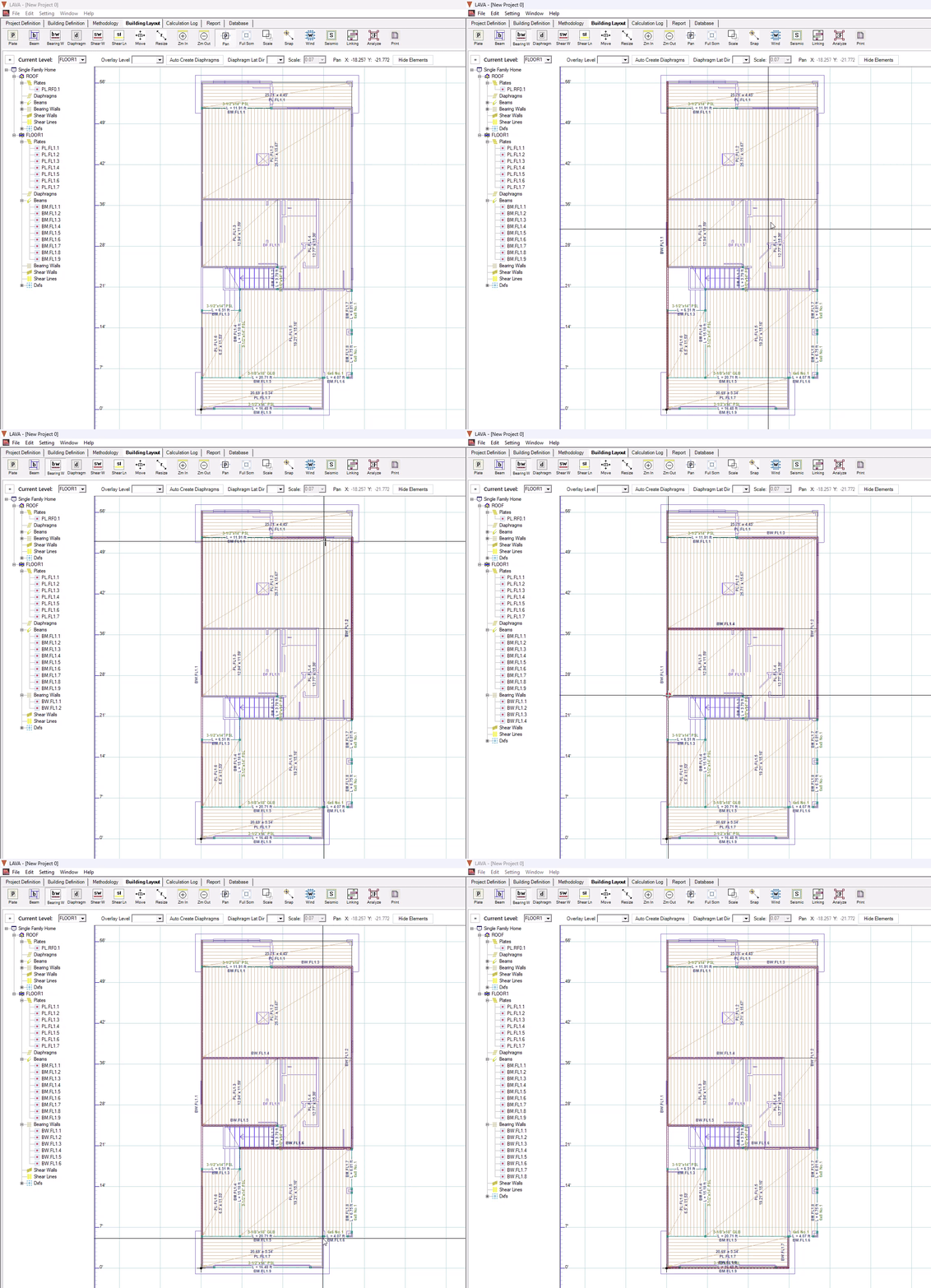
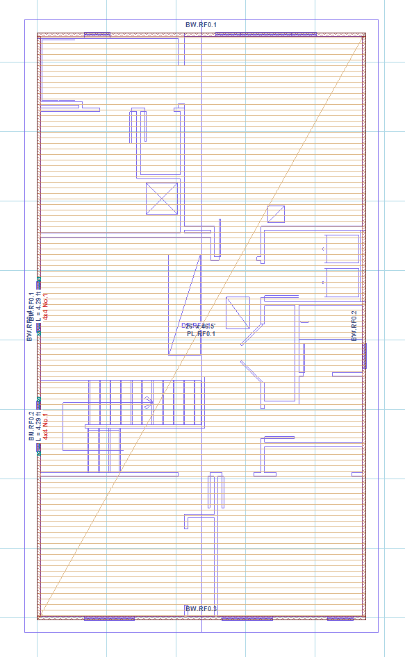
For your reference, the finished floor plans are shown below.
ROOF level:
FLOOR1 level:
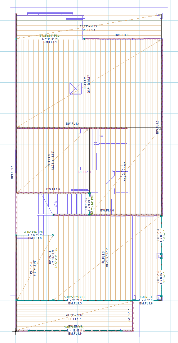
This concludes the gravity system modeling process.