Follow these step-by-step instructions to build a model in LAVA and achieve effective results, focusing on only what’s essential. You can follow along this tutorial with the inputs as shown in bullets.
Prefer to watch instead? You can also follow along with our step-by-step video tutorials.
Setting Up the Parameters
Project Definition
👉 Access the video to follow along with these steps below.
Open LAVA program and it should open to the first tab- Project Definition. This area is used mostly to define the title pages in the report.
Input project number, name, jurisdiction, state, subject, etc as shown below. These items will be part of the cover pages and it will show up on the header of all calculation report. For this tutorial, we input the following items, and leave the rest blank:
Project Number: 10000
Plan: 1
Project Name: Single Family Home
Jurisdiction: Modesto
State: CA
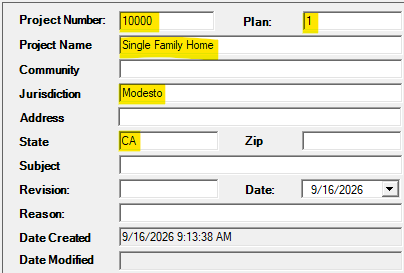
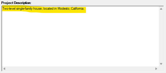
Project Description: This information will be part of the cover pages of calculation report. We input the following:
Project Description: Two-level single-family house, located in Modesto, California.
Criteria
Base Criteria
You can enter the Longitude, Latitude and Elevation fields, however these fields are for reference only and are optional.
Fill out the parameters as shown following, (these are defaults):
Building Code: IBC 24
Risk Category: II
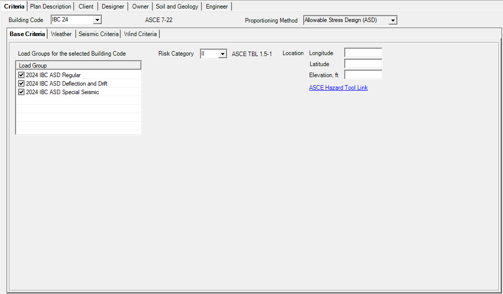
Note: The “ASCE Hazard Tool Link” button will launch your internet browser to allow you to enter the address of your site and provide you spectra response coefficients.
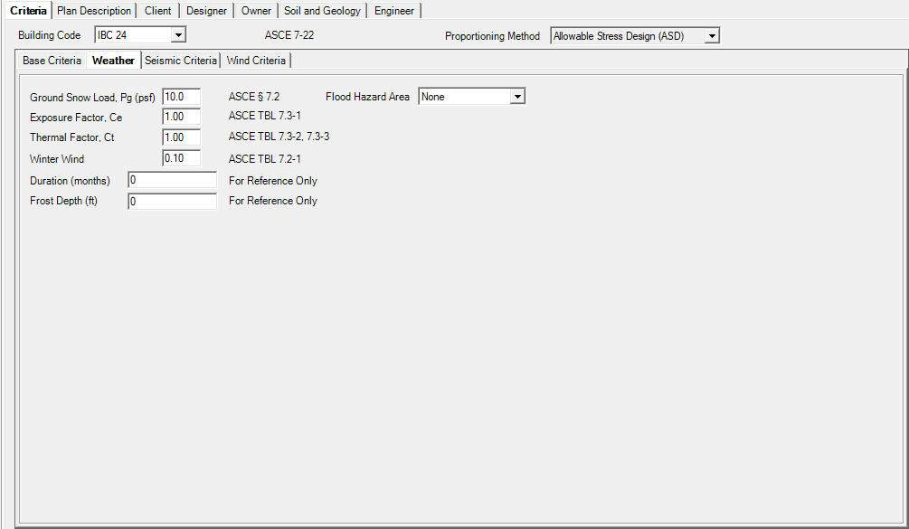
Weather
Enter the design parameters for snow load.
Snow load is not applicable at the location of tutorial project. Keep the default values in this tab for tutorial
Seismic Criteria
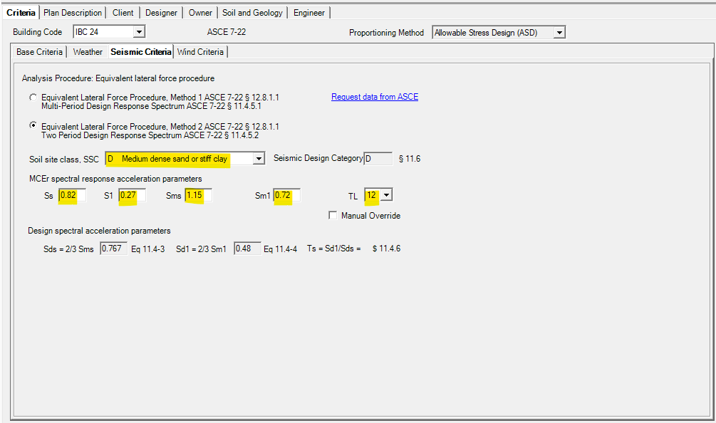
Enter the following site-specific values.
Analysis Procedure. Select second option: Equivalent Lateral Force Procedure, Method 2 ASCE 7-22 §12.8.1.1 Two Period Design Response Spectrum ASCE 7-22 §11.4.6
Soil site class, SSC. Select D Medium dense sand or stiff clay
MCEr spectral response acceleration parameters:
Parameter | Value |
|---|---|
Ss | 0.82 |
S1 | 0.27 |
Sms | 1.15 |
Sm1 | 0.72 |
TL | 12 |
Wind Criteria
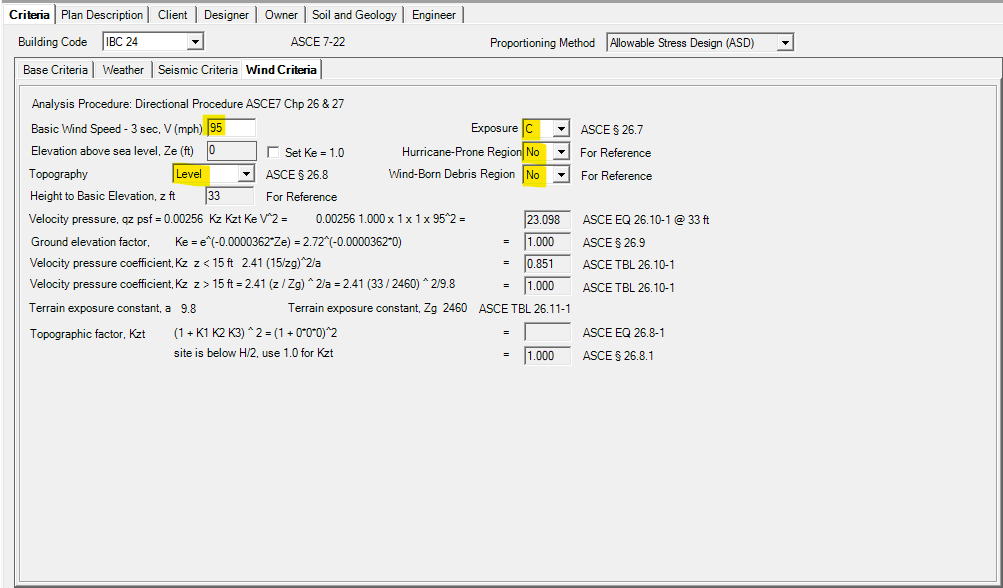
Fill out the parameters as shown following,
Basic Wind Speed - 3 sec, V (mph): 95
Exposure: C
Topography: Level
Hurricane-Prone Region: No
Wind-Born Debris Region: No
Plan Description
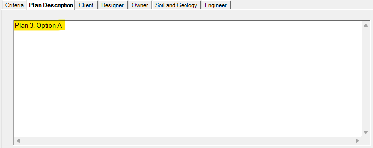
This information will be part of the cover pages of calculation report. The structure we are about to model is one option of a larger development, so we input some description here to distinguish with the other structures within the same development.
Plan 3. Option A
Client, Designer, Owner, Soil and Geology, Engineer
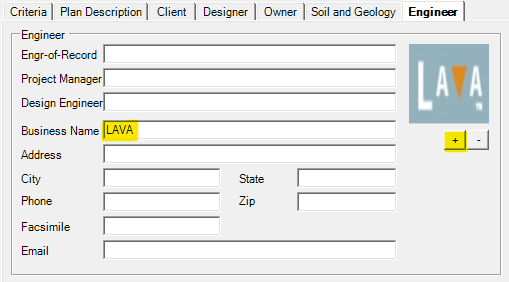
These items will be part of cover pages of calculation report if they are filled out. Engineer Business Name and logo will also show up on the header of all calculation report.
This step is optional if you do not have logo ready to upload.
Business Name: Add your business name here.
Add your Company Logo by clicking on “+”
Building Definition
👉 Access the video to follow along with these steps below.
Click the top tab called Building Definition to enter the building specific information.
Profile
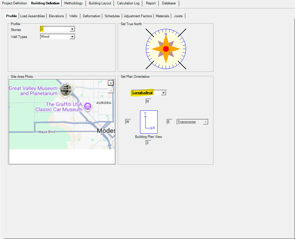
Select Stories: 2
Select Longitudinal direction to align with the ridge of main roof. In this tutorial, the main ridge is in Y direction.
Load Assemblies
There are preset loads ready for you to use in a Single-Family Residential building. The default loads are not applied until you click on the radio button to select them. Once you click on the radio button, it selects the default load for the building and used to calculate the seismic weight of the building. However, if you have more than one load assembly, you can use the other fields to set them up and apply them later to the model manually.
Roof Loading:
Select: Roof- SFR - MPC Truss- Tile
Set the Roof Slope: 4
Roof Slope 2: Scroll to the top of the list so that it’s empty and this will delete the slope**
Roof Slope 3: Scroll to the top of the list so that it’s empty and this will delete the slope**
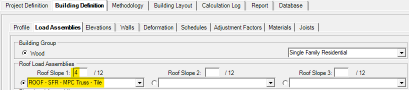
** The deletion of the additional loads is not required but it helps to see the applied load without confusion.
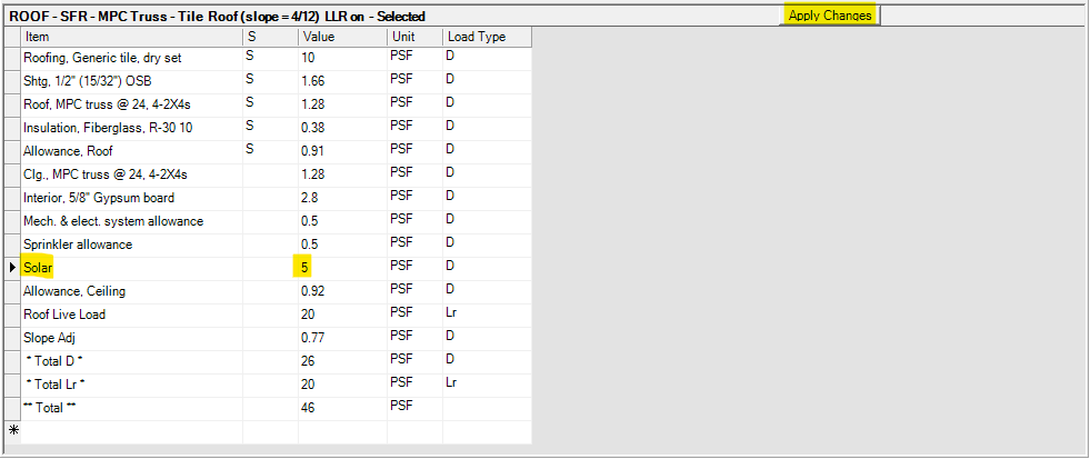
Adjust the loads by clicking on the Roof -SFR- MPC Truss - Tile
Replace “Item” with “Solar”
Value: 5 PSF
Click “Apply Changes”
Floor Loading:
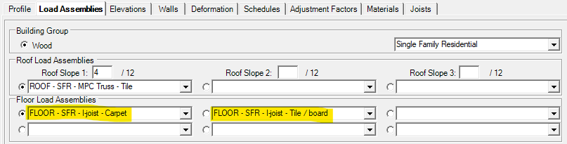
Select: Floor - SFR - I-Joist- Carpet as default with the radio button
Select: Floor - SFR - I-Joist - Tile/Board- this will be used later manually applied
Set all other floor loading to empty as described above
Wall Loads:
Select: EX WALL - SFR- Wood- Stucco
Select: IN WALL - SFR- Wood- Partition
Set all the other wall loadings to empty as described above.
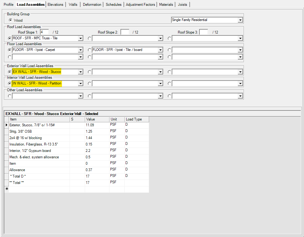
In this tutorial, we will not use Other Load Assemblies. However, they can be set and defined here and applied manually in the Building Layout.
Elevations
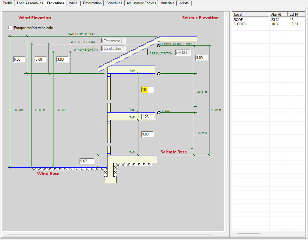
You can input mean roof height, plate height, and parapet height for wind calc if needed. For this model, we will increase the upper floor to accommodate higher ceilings.
Note: these elevations are established by default in the Preferences section.
Enter the following value:
Second Floor: 10 ft
Walls
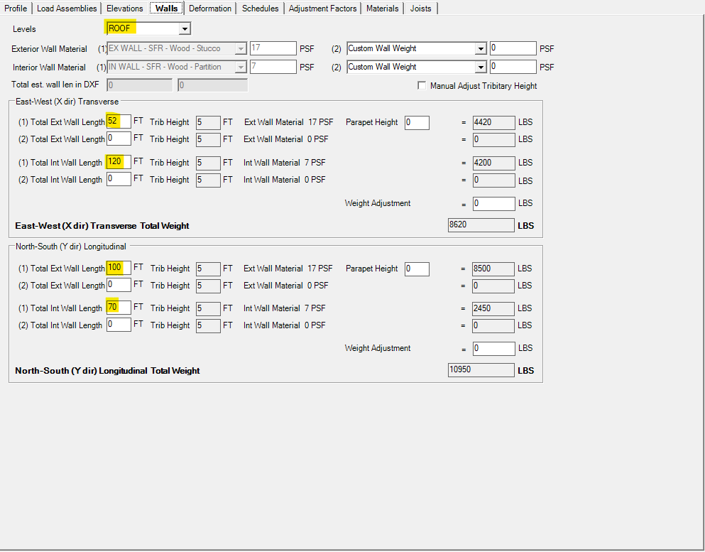
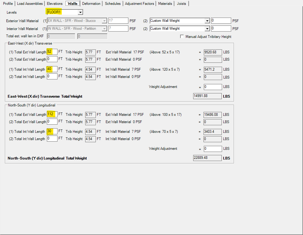
Input wall lengths for exterior walls and interior walls. This will be used to calculate seismic weight. For this tutorial, we input the following for the two levels:
Levels: ROOF
East-West (X dir) Transverse Total Ext Wall Length: 52
East-West (X dir) Transverse Total Int Wall Length: 120
North-South (Y dir) Longitudinal Total Ext Wall Length: 100
North-South (Y dir) Longitudinal Total Int Wall Length: 70
Levels: FLOOR1
East-West (X dir) Transverse Total Ext Wall Length: 52
East-West (X dir) Transverse Total Int Wall Length: 40
North-South (Y dir) Longitudinal Total Ext Wall Length: 112
North-South (Y dir) Longitudinal Total Int Wall Length: 30
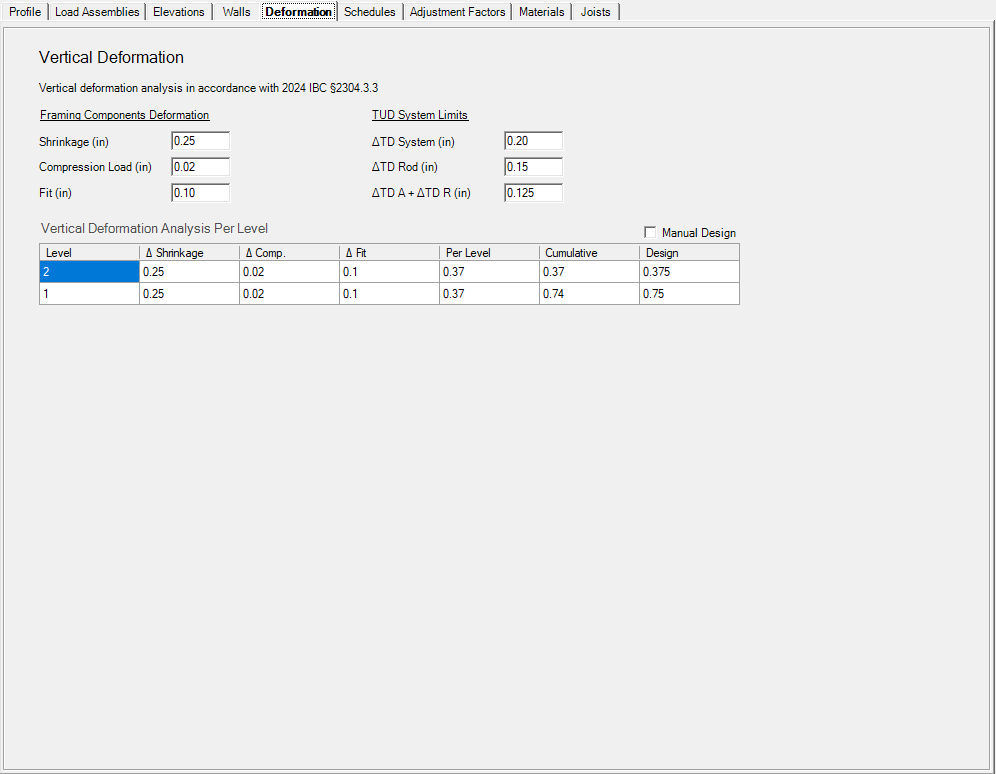
Deformation
Input the parameters to calculate the total deflection of tie-down system.
Keep the default values for tutorial
Schedules
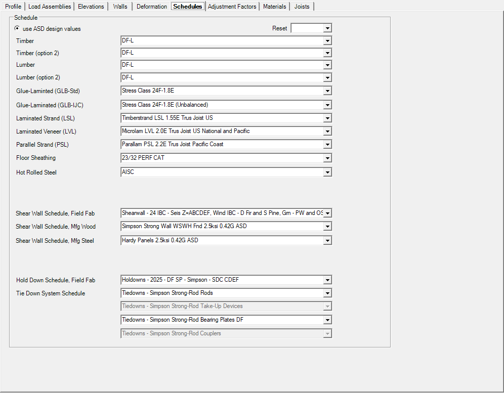
Select material species and grade for all items. The selection will be saved and non-editable once the LAVA file is saved. You can reset schedule and change options.
Adjustment Factors
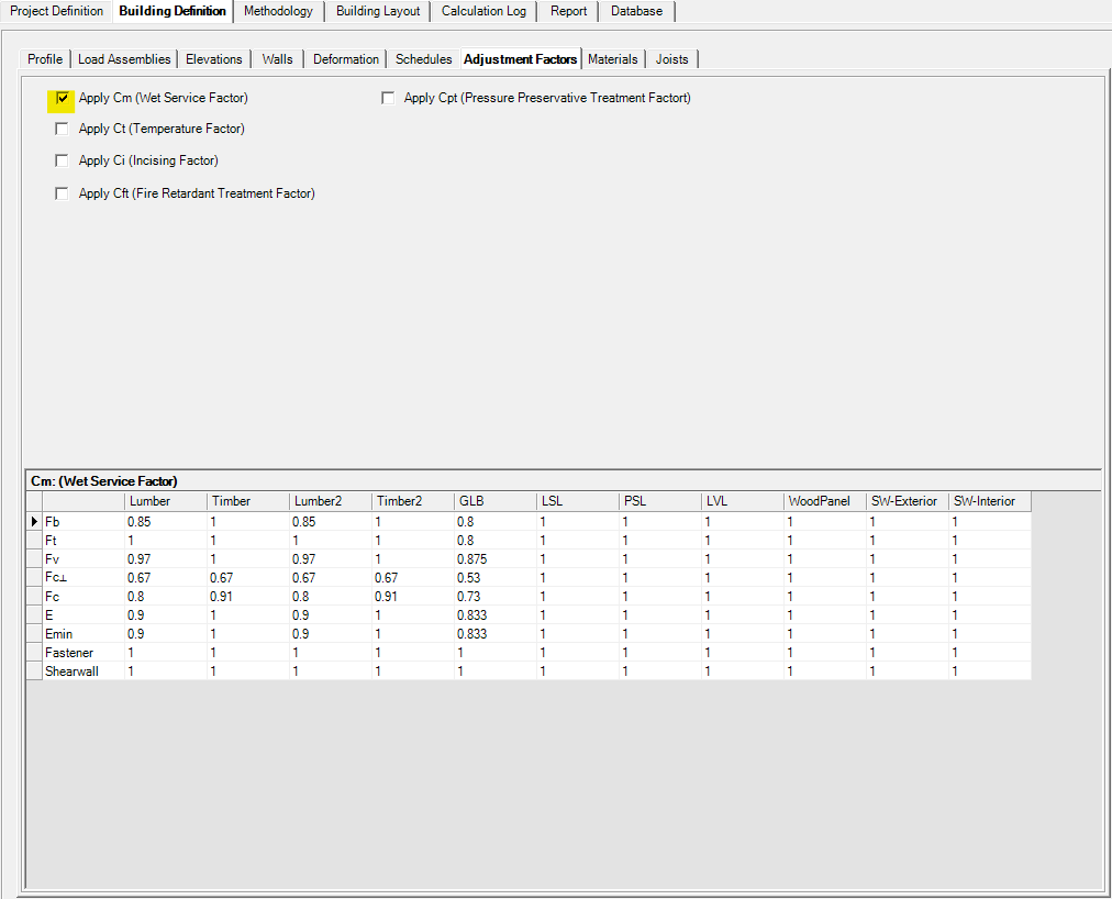
Select the applicable adjustment factors for the project. We include Wet Service Factor Cm for this project.
Materials
Input the description of the materials used in the project if you want to include it in calculation report. If you want to be consistent with construction drawings, you can use this area to enter these material notes, and an example is shown below.
Leave Materials blank for tutorial
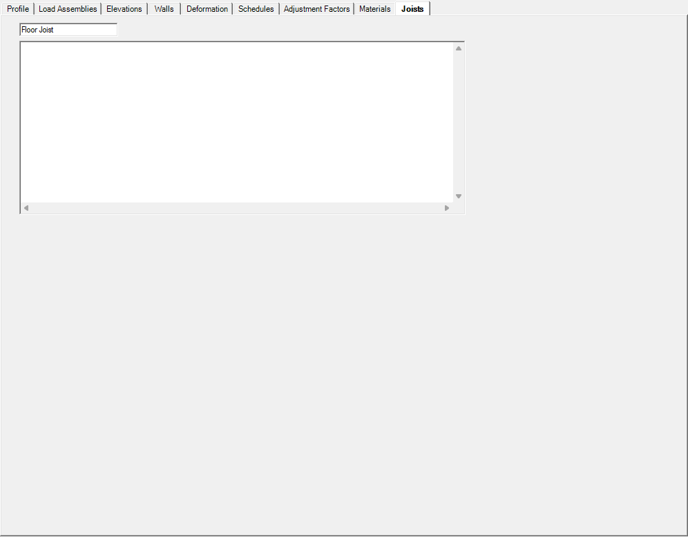
Joists
Input the description of the floor joists used in the project if you want to include it in calculation report. If you want to be consistent with construction drawings, you can use this area to enter the joist information, and an example is shown below.
Leave Joists blank for tutorial
Methodology
👉 Access the video to follow along with these steps below.
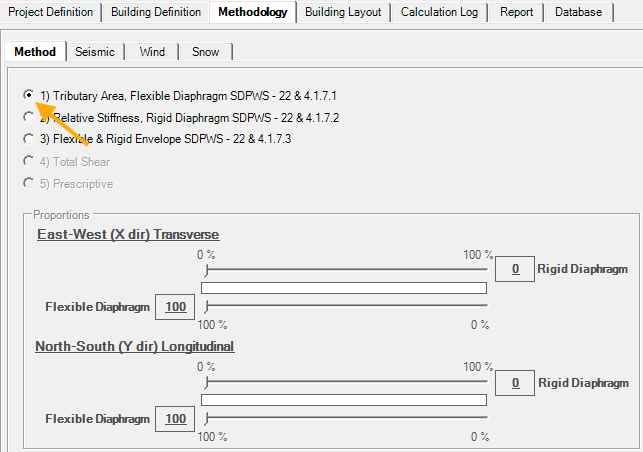
Method
You can choose what type of lateral analysis method: flexible, rigid, or envelope.
Select Flexible Diaphragm
Seismic
This will turn on the seismic load calculations and distribution for the project.
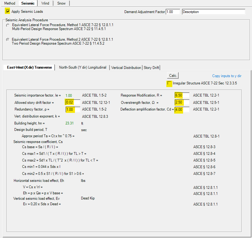
Select if redundancy factor is to be applied for the project. Select if drag struct calcs needs to consider irregularity of the structure. The rest of the values are pulled from Building Definition, or are default values for light frame wood structure if they are left unmodified. You can modify parameters here if needed, such as input 3.5 in R value if ordinary moment frame is present in this structure. For this tutorial, we are comfortable not to apply 1.3 redundancy factor or structure irregularity, so we left 1.0 for redundancy factor, and unchecked ‘Irregular Structure ASCE 7-22 Sec 12.3.3.5‘.
Click the "Apply Seismic Loads” (this is default)
East-West (X dir) Transverse
Fill out the fields as shown following:
Uncheck ‘Irregular Structure ASCE 7-22 Sec 12.3.3.5‘
Response Modification, R = 6.5 (this is default)
Allowed story drift factor = 0.02 (this is default)
Overstrength factor = 2.5 (this is default)
Redundancy factor = 1 (this is default)
Deflection amplification factor, Cd = 4.00 (this is default)
North-South (Y dir) Longitudinal
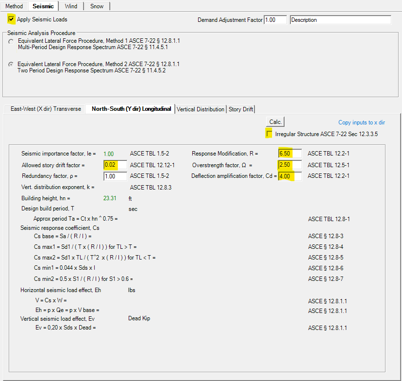
Fill out the fields as shown following:
Uncheck ‘Irregular Structure ASCE 7-22 Sec 12.3.3.5‘
Response Modification, R = 6.5 (this is default)
Allowed story drift factor = 0.02 (this is default)
Overstrength factor = 2.5 (this is default)
Redundancy factor = 1 (this is default)
Deflection amplification factor, Cd = 4.00 (this is default)
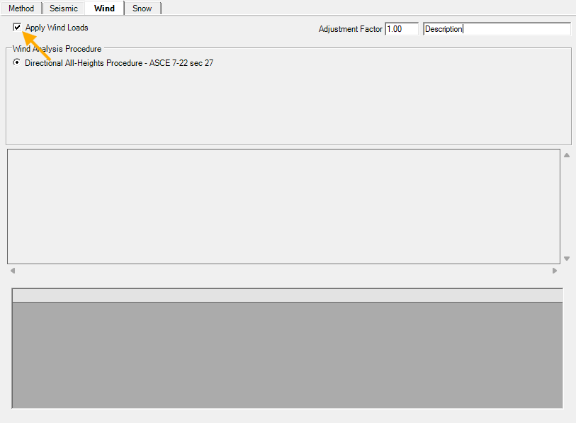
Wind
This will turn on the wind load calculations and distribution for the project.
Click the "Apply Wind Loads” (this is default)
Snow
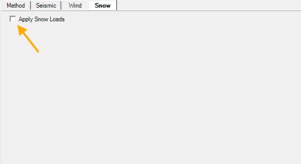
This will turn on the snow load calculated based on the Criteria setup in Project Definitions and snow loads distributed to the roof level for the project.
Uncheck this option for this tutorial.
Note: Snow loads do not apply drift loads at this time.