Determining the Torsional Irregularity Ratio Using LAVA
Torsional behavior is an important aspect of seismic design. When the distribution of lateral stiffness in a building is uneven, the structure can rotate as it deflects under seismic loading. This rotation produces additional displacement at the edges of the structure and must be evaluated to determine whether a torsional irregularity exists.
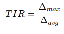
ASCE 7-22 defines the Torsional Irregularity Ratio (TIR) in Section 12.3.2.1.1 as:
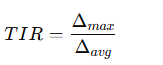
where:
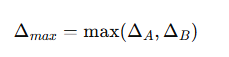
Δmax = Maximum story drift at the building edge
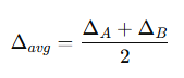
Δavg = Average story drift at the two opposing edges of the structure
The code states that torsional irregularity exists when:
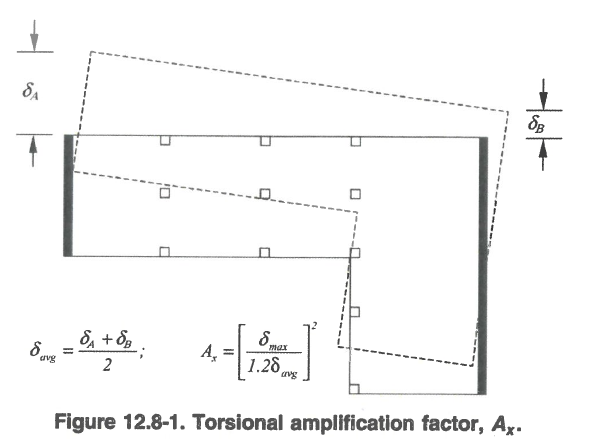
If this condition occurs, the effects of torsion must be amplified using the torsional amplification factor defined in ASCE 7-22 Section 12.8.4.3 and illustrated in Figure 12.8-1.
This article explains how to determine this ratio using results reported in LAVA.
Rigid Diaphragm Assumption in LAVA
For rigid diaphragm analysis, the diaphragm is assumed to distribute lateral forces to the vertical resisting elements based on their relative stiffness. Under this assumption:
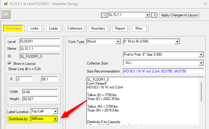
All shear walls along a shear line experience the same diaphragm displacement because the diaphgram is Rigid and the Shear Line is set to distribute loads based on “Stiffness”.
Individual wall deflections represent the drift of that shear line.
Because of this behavior, the drift at the building edges can be determined directly from the deflection reported for the exterior shear walls.
LAVA reports the deflection for each wall, allowing the engineer to determine the drift values required for the torsional irregularity calculation.
Determining Edge Drifts
To compute the torsional irregularity ratio:
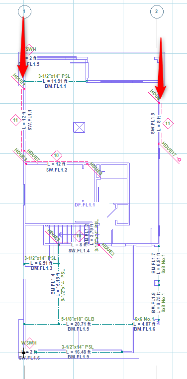
Identify the two outer edges of the structure in the direction of analysis.
Locate a exterior shear wall at those edges.
Obtain the wall deflection values reported by LAVA.
Because the diaphragm is assumed rigid, the deflection of any wall along that exterior shear line represents the drift of that building edge.
For example:
ΔA = Deflection of the wall at one building edge
ΔB = Deflection of the wall at the opposite building edge
The average drift is then calculated as:
The maximum drift is simply the larger of the two values.
The torsional irregularity ratio becomes:
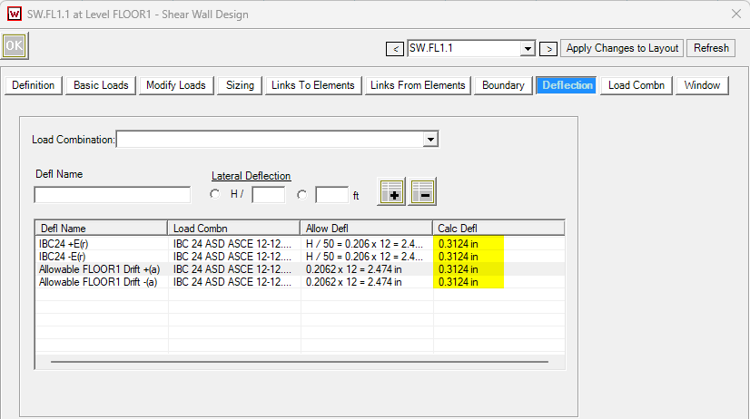
For example, below you can find the deflection for the exterior walls by clicking on the shear walls and going to the
You can find the maximum deflection listed in the Deflection tab:
Evaluating Torsional Irregularity
Once the ratio is computed:
TIR ≤ 1.2
No torsional irregularity exists.TIR > 1.2
The structure has a torsional irregularity according to ASCE 7-22 Table 12.3-1.
When this occurs, additional torsional amplification must be applied in the design shown below in LAVA.
Torsional Amplification Factor
When torsional irregularity exists, ASCE 7-22 Section 12.8.4.3 requires that accidental torsion effects be amplified by the factor:
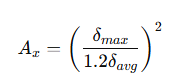
This factor increases the torsional moment applied to the structure to account for the uneven stiffness distribution.
Applying the Amplification in LAVA
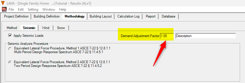
LAVA allows this amplification to be incorporated directly through the Seismic Demand Adjustment Factor.
When the torsional irregularity ratio exceeds 1.2:
Calculate the torsional amplification factor Ax
Enter this value into the Demand Adjustment Factor field in the seismic analysis settings.
This adjustment increases the seismic demand applied to the lateral system, ensuring that torsional amplification effects are included in the design.
Summary
LAVA provides the wall deflection results necessary to evaluate torsional irregularity directly from the analysis output. The process consists of:
Identifying the exterior shear walls at the edges of the building.
Obtaining the wall deflection values reported by LAVA.
Calculating the average and maximum edge drift.
Computing the Torsional Irregularity Ratio (TIR).
Applying the torsional amplification factor when the ratio exceeds 1.2.
This workflow allows engineers to quickly verify torsional irregularity and incorporate the required amplification directly into the seismic design process.