Linking logic overview
LAVA uses “links” to move forces from one element to another. There are two ways links are created:
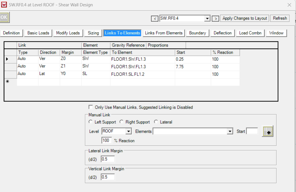
1) Auto Links (default)
Auto Links are created by LAVA based on typical/expected load paths.
Pros: fast, consistent, less setup.
Cons: not every unusual condition is handled perfectly (for example: linking a reaction into multiple diaphragms of different sizes in a very specific way).
2) Manual Links (user-defined)
Manual Links are created by the user in the Link to Elements table.
Pros: full control for nonstandard load paths and validation scenarios.
Cons: easy to create confusing behavior if the user mixes link targets in a way LAVA was not designed to support.
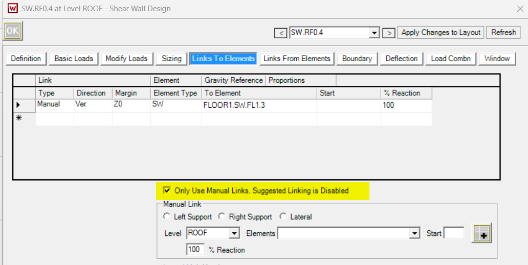
“Use Only Manual Link”
Intended behavior
When the user checks Use Only Manual Link:
Auto Links should be ignored/disabled for that element.
After solution, the Auto Links will disappear from this element.
Only the user’s Manual Links should apply.
Practical guidance
If the user wants Auto + Manual together, they should not check “Use Only Manual Link.”
If they want the element to behave only according to the Manual Links, they should check it.
In other words:
Checked = manual-only behavior
Unchecked = auto links remain, manual links can be added alongside them
Linking SW reaction to multiple diaphragms
Auto link behavior
Auto Links will distribute the same type of reaction equally, even when diaphragms differ in size.
If you wish to adjust the distribution of the loads, switch from Auto and use Manual Links shown below.
In this example, both DP.FL1.Y1 and DP.FL2.Y1 will receive 500lbs Y direction load from the SW above if the Auto link behavior.
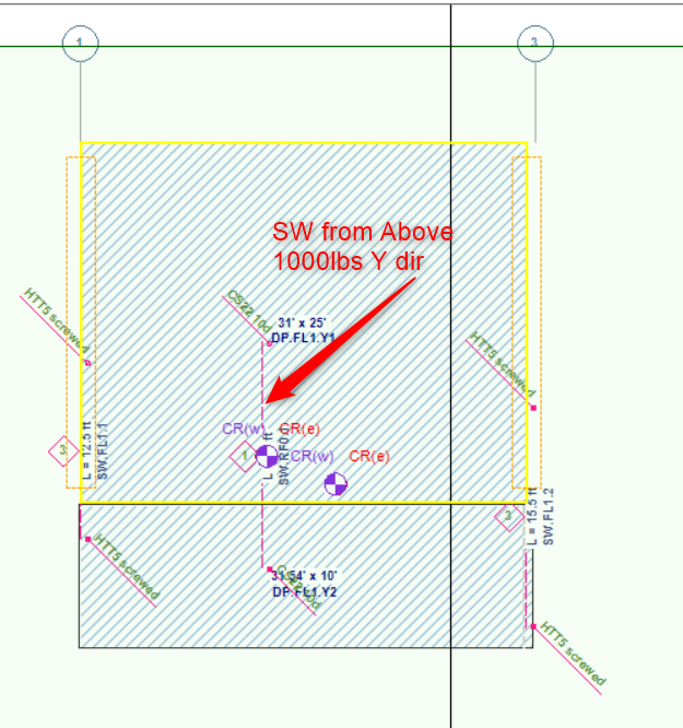
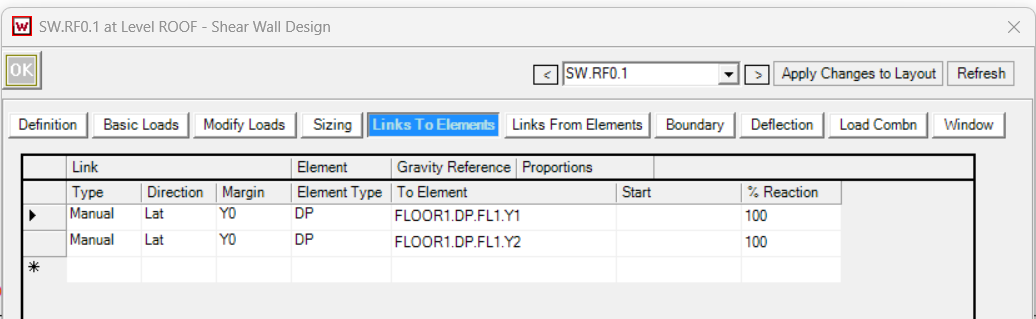
Manual link behavior
If a reaction is linked to multiple diaphragms manually, LAVA distributes the reaction based on diaphragm geometry (proportional to diaphragm “length” in the link direction).
Example:
Two diaphragms below receive load in proportion to their lengths:
Lengths: 25 ft and 10 ft
Total = 35 ft
Total reaction = 1000 lb
Distribution:
Diaphragm 1: 1000 × (25 / 35) ≈ 714lb
Diaphragm 2: 1000 × (10 / 35) ≈ 285 lb
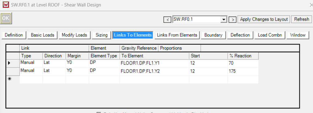
Force Equal Distribution- Manual Link
You can designate exactly how you want the loads to be distributed to the diaphragms below by using the % Reaction.
Example:
Two diaphragms below receive load in proportion to their lengths:
Lengths: 25 ft and 10 ft
Total = 35 ft
Total reaction = 1000 lbs x 50% = 500lbs
Adjust Distribution by percentage:
Diaphragm 1: 500 / 714 ≈ 70%
Diaphragm 2: 500/ 285 ≈ 175%
“% Reaction” in Manual Links
How does this work?
The link first determines the diaphragm’s portion of the reaction (based on distribution rules).
Then “% Reaction” scales that portion.
So:
100% = “send the calculated portion”
150% = “send 1.5× the calculated portion”
It can exceed 100% intentionally.
Why it was designed this way
In most cases, this is used to show automatic distribution. The ability to change this distribution is for edge cases where a user is intentionally adjusting distribution for a specific use-case (for validation exercises, unusual load paths, or matching a specific expected hand distribution).
What “Start” means by Element
Diaphragms:
“Start” defines where the point force is applied along the diaphragm length.
Simple interpretation:
A force applied at a point along a diaphragm creates end reactions based on lever arm.
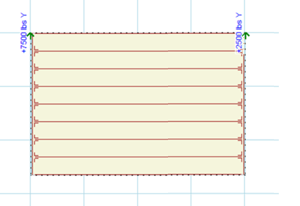
Example: diaphragm length = 40 ft
Load applied at 10 ft from the start
Then reactions are based on 10 ft and 30 ft segments:
Reaction at far end ≈ (10/40)*P or (30/40)*P depending on which end is “start”
Example: 30/40 × 10 kips = 7.5 kips at one end, 2.5 kips at the other
The key point:
Start is a location input, not a scaling factor.
It affects how the diaphragm end reactions split, not the total force.
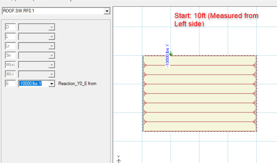
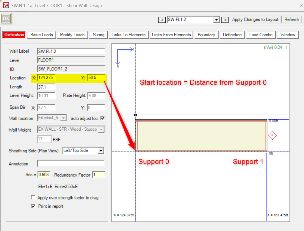
Shear Walls:
“Start” defines where the load will be applied measured from the Support 0 location. Note: If the Auto-link is turned on and walls are stacked, you’ll see that the loads transfer at the HD Offset location from Support 0 (Default 0.25’).
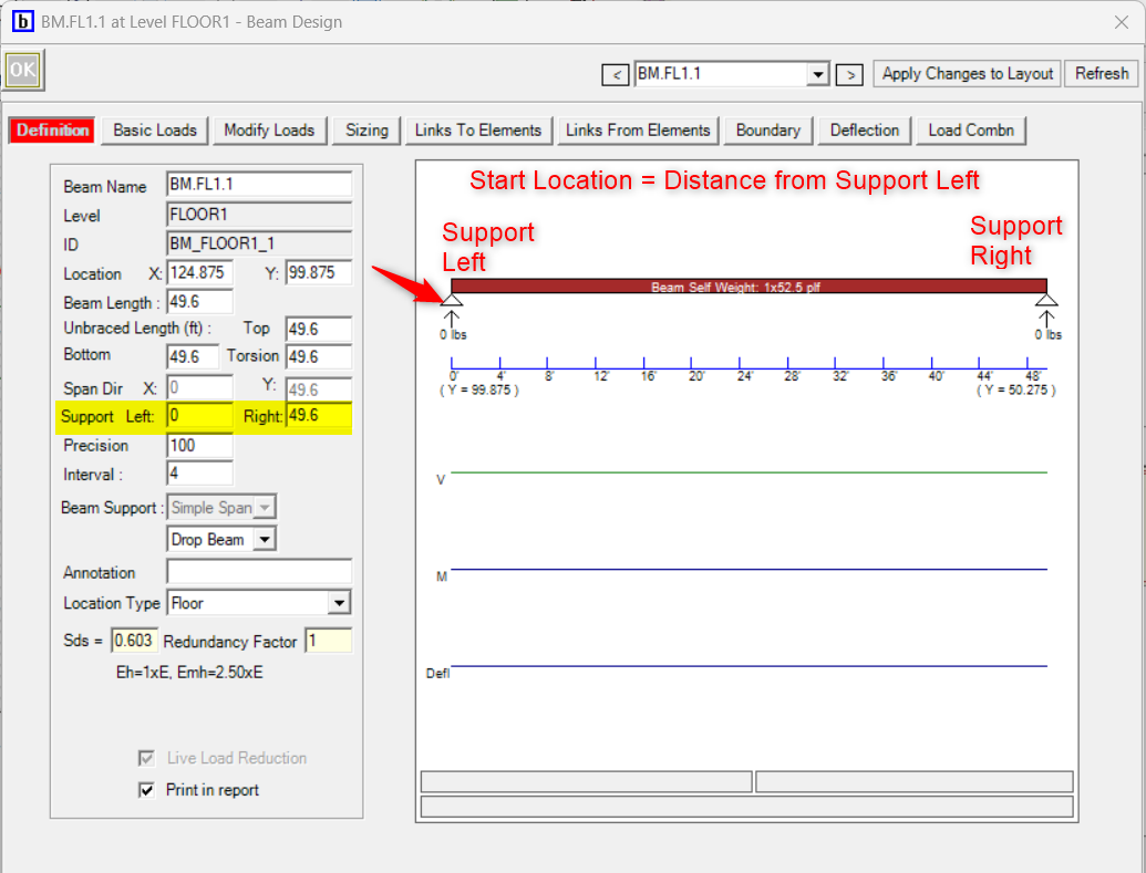
Beams:
“Start” defines where the load will be applied measured from the Support Left location.
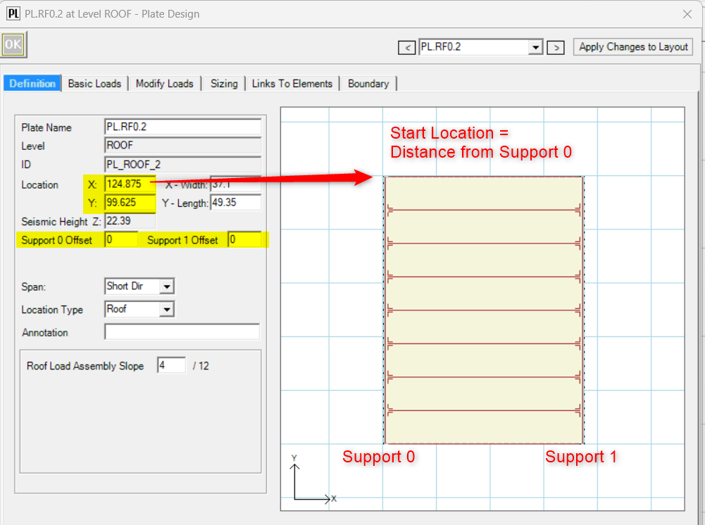
Plates:
“Start” defines where the load will be applied measured from the Support 0 location.
Beam Reaction Linking
A beam reaction will not be automatically linked to more than one supporting beam. This was done to avoid duplicate loads entering the system (double counting in the load pool).
If the user truly needs one reaction to go to multiple members
They can do it with manual linking, but they need to understand the distribution rule:
When a beam reaction is manually linked to multiple beams, the force is split equally among those supporting beams:
Each supporting beam receives Force / Number of supporting beams
This is a simplified assumption, but it is predictable and prevents accidental duplication.
Shear Wall Linking
The design intent
With shear lines in the model, the intent is:
Shear wall reactions should transfer to the shear line, not to both the shear line and the individual shear walls.
This is why, in practice, LAVA should not be asked to “split” a shear wall reaction into:
part to a shear line and
part to shear walls directly
If the user wants to bypass shear lines and go directly to shear walls, the clean way to do it is:
Use Only Manual Link
Manually link to the target shear walls
Do not link that same reaction to a shear line at the same time
Recommended modeling workflow
If your goal is a clean, explainable load path that matches how LAVA is designed:
Use shear lines as the collector for lateral loads where possible.
Let Auto Links do the load distribution and tracking.
Use Manual Links only when:
A load is going to the wrong diaphragm/region, or
You need to demonstrate/validate a specific distribution, or
The model is nonstandard (offset diaphragms, unusual transfer conditions, etc.)
If you need manual control, turn on Use Only Manual Link for that element, so you’re not fighting auto behavior.