Steel moment frames do have some use in light-frame construction. Although LAVA does not calculate moment frames, we can model shear walls as ‘place-holder’ elements to obtain lateral loading data generated by LAVA, and use them as input in external software or spreadsheets.
Obtain Lateral Loads for Place-Holder Elements
The lateral loading data are listed in Shear Wall Design dialog, under ‘Sizing’ tab, marked as ‘E Shear Line Load Y’, or ‘W(+)/(-) Shear Line Load Y’.
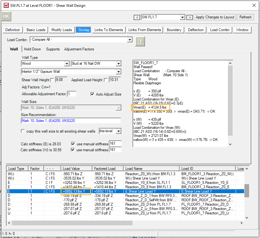
In the screenshot above, the unfactored seismic load is 5892.13 lbs. You can also obtain the strength level load from the ‘Vmax(E)’ as well: 4124.5 lbs / 0.7 = 5892 lbs. The seismic loading data may need modifications before applying in other software or spreadsheets.
Let’s consider a few scenarios:
Three-Story Structure, With Steel Special Moment Frames in All Exterior Walls at All Levels in X Direction
.png)
Per ASCE7-16 12.2.2, different R-value shall apply to each of the two orthogonal axes of the structure. Please go to ‘Design Procedure’ → ‘Seismic’ tab, and input the correct R-value. In this case, input 8 as shown below.
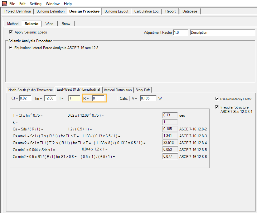
With the operation above, LAVA will calculate all shear walls in X direction with 8 as R-values. No modifications of lateral loading data are necessary.
Three-Story Structure, With One Steel Special Moment Frame in Exterior Walls at All Levels in X Direction
.png)
Per ASCE7-16 12.2.3, where different seismic force-resisting systems are used in the same direction, the most stringent applicable (lowest R-value) shall apply. In this case, input 6.5 as shown below. (Please note: 6.5 is default R-value in LAVA. If you leave this field blank, LAVA will use 6.5 in full structure analysis.)
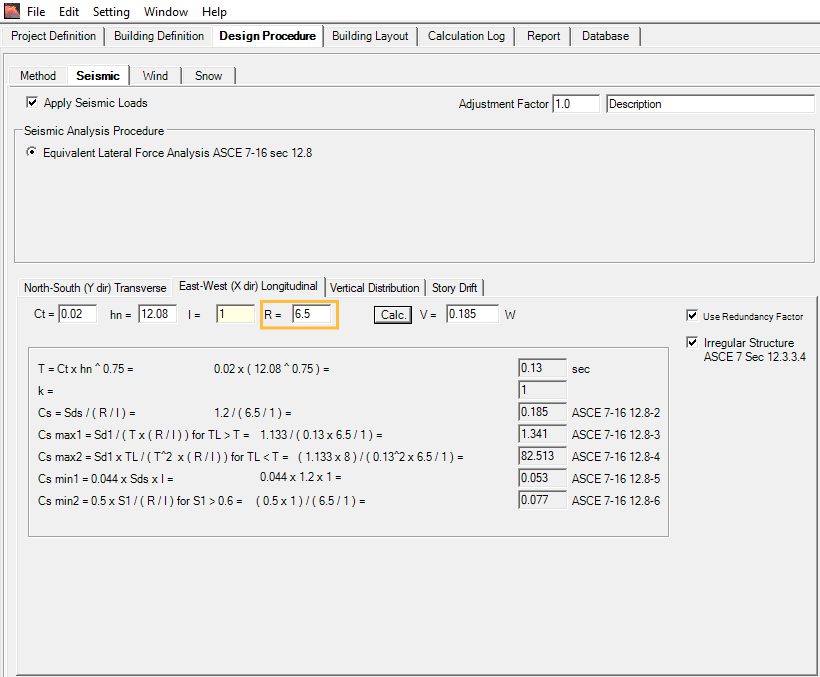
With the operation above, LAVA will calculate all shear walls in X direction with 6.5 as R-values. No modifications of lateral loading data are necessary.
Three-Story Structure, With One Steel Special Moment Frame in Exterior Wall at Ground Level in X Direction
.png)
Per ASCE7-16 12.2.3.1.2, where a structure has a vertical combination in the same direction, and where the upper system has a lower R-value, the design coefficient (including R-value) for the upper system shall be used for both systems. In this case, input 6.5 as shown below. (Please note: 6.5 is default R-value in LAVA. If you leave this field blank, LAVA will use 6.5 in full structure analysis.)
With the operation above, LAVA will calculate all shear walls in X direction with 6.5 as R-values. No modifications of lateral loading data are necessary.
Three-Story Structure, With One Steel Ordinary Moment Frame in Exterior Wall at Ground Level
.png)
Assuming steel ordinary moment frame is permitted in the project seismic design category, per ASCE7-16 12.2.3.1, where a structure has a vertical combination in the same direction, and where the lower system has a lower R-value, the design coefficient (including R-value) for the upper system is permitted to use higher R-value, while only the lower level uses the lower R-value. In this case, it is advised to keep 6.5 as R-value, and make adjustment in reaction of the shear walls (including the place-holder element) on the ground level.
With the operation above, LAVA will calculate all shear walls in X direction with 6.5 as R-values. All shear walls’ seismic loading on ground level, including regular plywood shear walls and the ordinary steel moment frame, shall be increased by ratio of 6.5 / 3.5 = 1.86.
One-Story Structure, Light Frame Construction, With One Steel Ordinary Moment Frame in Exterior Wall
.png)
Assuming steel ordinary moment frame is permitted in the project seismic design category, per ASCE7-16 12.2.3.3 Exception, it is permitted to use different R-value for each independent line of resistance (‘shear line’ in LAVA). In this case, it is advised to keep 6.5 as R-value, and make adjustment in reaction of the place-holder element on the ground level, leaving the rest of the shear walls alone.
With the operation above, LAVA will calculate all shear walls in X direction with 6.5 as R-values. The seismic loading of the ordinary steel moment frame shall be increased by ratio of 6.5 / 3.5 = 1.86.
Mix and Match Plywood Shear Wall and Moment Frame within the Same Shear Line
.png)
It is not a good idea to combine plywood shear walls and steel moment frames within the same shear line due to the great difference in stiffness. If this must be done for certain reasons, you can modify the stiffness of the place-holder element in LAVA to imitate a steel frame.
The stiffness can be adjusted in Shear Wall Design dialog, under ‘Sizing’ tab:
.png)
For regular plywood shear wall, the stiffness is calculated and listed. To override with custom stiffness, you can check ‘use manual stiffness’ option, and enter the value:
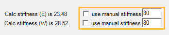
The stiffness in LAVA is defined as ‘unfactored force / deflection (load combination E)’ with unit in kips/inch. You may obtain the stiffness of moment frame from other software or spreadsheets, and please make sure the value you are inputting is also in kips/inch.
Open the Shear Line Design dialog, and go to ‘Definition’ tab. Please make sure the ‘Distribute by’ shows ‘Stiffness’ in the drop-down menu. This will insure the shear force collected by this shear line will be distributed by stiffness, and all shear wall elements in this shear line will have the same deflection per Special Design Provision For Wind And Seismic 4.3.3.4.1.
The seismic loading of the shear walls and the moment frame may be increased per ASCE 7-16 12.2.2, or 12.2.3.1.1, depending on the structure configuration.
Example
We will go over an example using manual stiffness in LAVA to address shear lines that mix-and-match plywood shear wall and moment frame. Please note, this is simply a demonstration of a potential approach. Please use engineer’s judgement in actual projects.
This example is a one-story building, with one shear line that has both special steel moment frame and plywood shear wall.
Under Project Definition - Criteria - Wind tab, input Basic Wind Speed: 105 mph, Exposure: C, Topography: Level
.png)
Under Project Definition - Criteria - Seismic tab, input Seismic Parameters: S1 = 0.454, Ss = 1.277, Site Class: D-Default
.png)
Under Building Definition - Load Assemblies tab, define flat roof with roof assembly with 20psf Dead Load, and 20psf Roof Live Load.
.png)
Under Building Definition - Load Assemblies tab, define exterior wall assembly with 17psf Dead Load.
.png)
Under Building Definition - Elevation tab, define elevation with 2.5’ parapet roof, and plate height with 10.08’.
.png)
Under Building Definition - Walls tab, input 40’ for exterior and interior wall length in X direction; and 64’ for exterior wall length and 30’ for interior wall length in Y direction.
.png)
Under Design Procedure - Method tab, select flexible diaphragm.
.png)
Under Building Layout tab, model a 20’x32’ plate.
.png)
Under Building Layout tab, in X direction, model a 20’x32’ diaphragm.
.png)
Under Building Layout tab, in Y direction, model a 20’x32’ diaphragm.
.png)
Under Building Layout tab, model two 4’ long shear wall on the bottom side of the floor plan; model 10’ long shear walls on the left and right side of the floor plan; model a 3’ long shear wall, and a 10’ long shear wall as a place-holder (named as SMF) on the top side of the floor plan.
.png)
Under Building Layout tab, model shear lines on both sides of the floor plan.
.png)
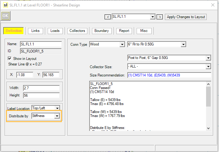
Open Design dialog of Shear Line A, and go to Definition tab. Select ‘Stiffness’ as distribution method.
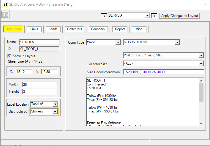
Click
.png) to run a full structure analysis. Afterwards, open Design dialog of the place-holder (SW.RF0.1), and go to Sizing tab. The unfactored seismic load (strength level) is 1783.87 lbs.
to run a full structure analysis. Afterwards, open Design dialog of the place-holder (SW.RF0.1), and go to Sizing tab. The unfactored seismic load (strength level) is 1783.87 lbs.
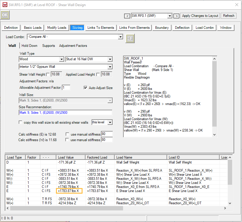
Model a 15’ long, 10’ tall one story one bay special moment frame with fixed base in your preferred program for ASD frame analysis, and input 1.784 kips seismic load, and obtain the frame displacement with load combination E. In our example, we obtain 0.115” displacement from RISA 3D.
Calculate the stiffness (kips/in) by dividing unfactored seismic load with displacement: 1.784 / 0.115 = 15.51
Check ‘use manual stiffness’ for seismic loads, and input 15.51, and click
to run a full structure analysis for the second time. Under Sizing tab, please note that the unfactored seismic load is updated to 1815.12 lbs.
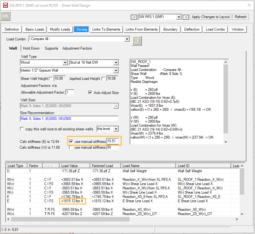
Return to the ASD frame analysis program, update the seismic load to 1.815 kips, and obtain the updated frame displacement with load combination E. In our example, we obtain 0.117” displacement from RISA 3D.
Calculate the updated stiffness (kips/in) by dividing unfactored seismic load with displacement: 1.815 / 0.117 = 15.53. We can consider the stiffness has converged, and the lateral loads are reasonably distributed within this shear line.
For more complicated projects, more iterations may be necessary to obtain the acceptable stiffness.