Drawing Diagrams Around Openings in X and Y Directions
When a diaphragm contains an opening, such as a stairwell or shaft, you can add openings to the diaphragm to account for it. In LAVA, this is accomplished by drawing sub-diaphragms in smaller rectangular subsections and adjusting their support offsets so the loads transfer back to the intended support lines.
This article explains how to model openings in both the X and Y directions and how load distribution behaves for flexible and rigid diaphragms.
General Approach to Modeling Openings
LAVA creates X-direction and Y-direction diaphragm diagrams as rectangular sections. In many projects, especially with flexible diaphragms, engineers choose not to explicitly model small openings.
For seismic design, leaving the diaphragm continuous is often conservative because you are effectively including slightly more seismic mass. For wind design, if the opening is internal and not exposed to wind pressure, it typically does not affect the applied lateral loads. In these situations, modeling the opening is not always necessary.
That said, openings can be modeled when greater precision is important. This is especially relevant when:
The opening meaningfully reduces diaphragm area.
Load paths directly adjacent to the opening need to be captured accurately.
The diaphragm is modeled as rigid and stiffness distribution matters.
For rigid diaphragms in particular, excluding an opening can artificially increase diaphragm stiffness and influence the calculated center of rigidity. If the opening is significant, modeling it will provide a more accurate representation of force distribution and torsional behavior.
How to Model the Diaphragm Openings
These are the steps to model the openings:
Break the diaphragm into smaller rectangular diagrams around the opening.
Assign each diagram to its intended support lines.
Offset the diagram supports as needed so loads transfer back to the correct shear lines.
This approach allows you to:
Maintain accurate tributary areas.
Control the force path around the opening.
Preserve realistic diaphragm behavior.
Example: Stairwell Opening
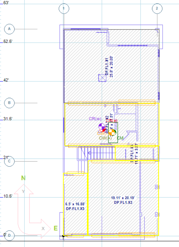
In this example, a stairwell opening interrupts the floor diaphragm. We will model diaphragm segment DPSL1.X4 so its forces transfer correctly to adjacent shear lines B & C.
Step 1: Draw Diagrams Around the Opening
Create rectangular diaphragm segments that frame the opening.
Do not allow the diagram to span across the void.
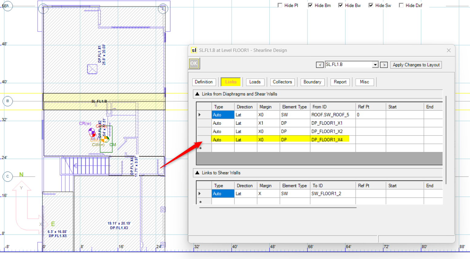
Step 2: Adjust Support Offsets
Double-click on diagram DPSL1.X4 to open its properties.
In this example:
The diaphragm support line must transfer load back to the B shear line.
The diagram’s support points are offset beyond the diaphragm boundary so they align with the correct structural support.

Offset Configuration:
First support 0 Offset: –12 ft
Apply the offset.
The support line moves 12 ft in the negative direction to reach the B shear line.
After applying both offsets, the diagram will visually show its support points extending outside the diaphragm footprint to connect with the intended shear lines.
Step 3: Verify Force Transfer
Once offsets are applied:
Lateral forces from this diaphragm segment will transfer to the adjacent shear lines.
Review the shear line forces to confirm proper load distribution.
Modeling in the Y Direction
Draw rectangular Y-direction diagrams around the opening.
Assign support lines appropriately.
Use support offsets to reconnect the diaphragm segment back to its correct shear lines.
The geometry changes direction, but the workflow remains identical:
Segment around the opening.
Offset supports to the true structural shear lines.
Confirm that forces transfer correctly.
Load Distribution Behavior
The way loads distribute depends on whether the diaphragm is modeled as Flexible or Rigid.
Flexible Diaphragm
For a flexible diaphragm:
Loads transfer directly to shear lines.
Distribution is based on tributary area.
Each segmented diaphragm contributes load proportionally to its supported shear lines.
Openings reduce tributary area. As a result:
Shear lines adjacent to the opening may see reduced load.
The total load path reflects only the remaining diaphragm area.
Rigid Diaphragm
For a rigid diaphragm:
LAVA calculates the center of rigidity (CR).
The diaphragm stiffness matrix includes the reduced geometry due to the opening.
Removing diaphragm area shifts the center of rigidity.
When an opening is present:
The CR may move toward stiffer regions.
Torsional effects may increase.
Shear line forces can redistribute accordingly.
This makes correct modeling of diaphragm segmentation especially important in rigid diaphragm analysis.
Best Practices
Determine if the opening is significant enough to model. For flexible diaphragms, this is not usually necessary.
Use support offsets intentionally and verify visually that supports align with the intended shear lines.