LAVA calculates seismic forces for shear wall, diaphragm, and collector design as part of the lateral analysis. These forces can be reviewed in the Shear Lines section of the calculation report.
This article explains how these forces are calculated and how LAVA distributes collector forces along a shear line, with reference to ASCE 7-22.
Example Model
The example used in this article is a two-story single-family home. You can download the tutorial model here:
The seismic force summary is shown in the Shear Lines section of the calculation report.
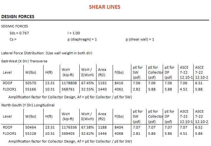
Note: Wind loads are not shown in this table because the determination for wind forces is the wind load only.
Understanding the Seismic Force Columns
LAVA reports several seismic force values because the forces used for shear wall, diaphragm, and collector design are not necessarily the same.
LAVA Result | Purpose |
|---|---|
pE for SW (psf) | Seismic force used for shear wall design |
pE for Collector (psf) | Seismic force used for collector design |
pE for DP (psf) | Seismic force used for diaphragm design |
Af | Amplification factor used to convert the shear wall seismic force to the collector seismic force |
All values shown are nominal seismic forces before application of the ASD 0.7 factor or other load-combination factors.
pE for SW (psf)
pE for SW is the seismic force used for shear wall design at each level. It is based on the seismic forces determined in accordance with ASCE 7-22 §12.8 and the vertical distribution of seismic force through the structure.
For example, for the X direction at FLOOR1:
Level seismic force = 4,061 lb
Diaphragm area = 1,440 ft²
Therefore:
pE for SW = 4,061 / 1,440 = 2.82 psf
pE for DP (psf)
pE for DP is the seismic force used for diaphragm design in accordance with ASCE 7-22 §12.10.1.1.
LAVA evaluates the diaphragm design force calculated using Equation 12.10-1 and the minimum force required by Equation 12.10-2, subject to the maximum diaphragm force requirements of Equation 12.10-3.
For FLOOR1 in the X direction, Equation 12.10-1 gives:

The resulting diaphragm force is converted to a pressure by dividing by the diaphragm area.
The minimum diaphragm force required by Equation 12.10-2 is:

For this example:
Fpx,min = 0.2 × 0.767 × 1.0 × 55,166 = 8,462.5 lb
Converting to pressure:
pE = 8,462.5 / 1,440 = 5.88 psf
Because the minimum diaphragm force controls in this example, LAVA uses 5.88 psf for diaphragm design.
pE for Collector (psf)
pE for Collector is the seismic force used to determine collector demand at each level in accordance with ASCE 7-22 §12.10.2.
For a regular structure, this force may be the same as the diaphragm design force. Where applicable seismic irregularities are selected under Methodology > Seismic, LAVA accounts for the required increase in collector forces.
Collector Amplification Factor, Af
LAVA expresses the relationship between the shear wall seismic force and collector seismic force using an amplification factor:
Af = pE for Collector / pE for SW
This factor allows LAVA to determine the collector demand associated with the seismic force carried by an individual shear line.
For example:
ROOF, Y direction:
Af = 7.07 / 7.07 = 1.00
FLOOR1, Y direction:
Af = 5.86 / 2.81 = 2.08
The FLOOR1 collector force is therefore greater than the seismic force used for shear wall design. The following examples show how LAVA applies this factor and distributes the resulting collector force along the shear line.
Shear Line 1 on ROOF Level
Shear Line 1 on ROOF Level (SL.RF0.1) is in Y direction, therefore pE for SW is 7.07, pE for Collector is 7.07, and Amplification factor is 7.07 / 7.07 = 1.
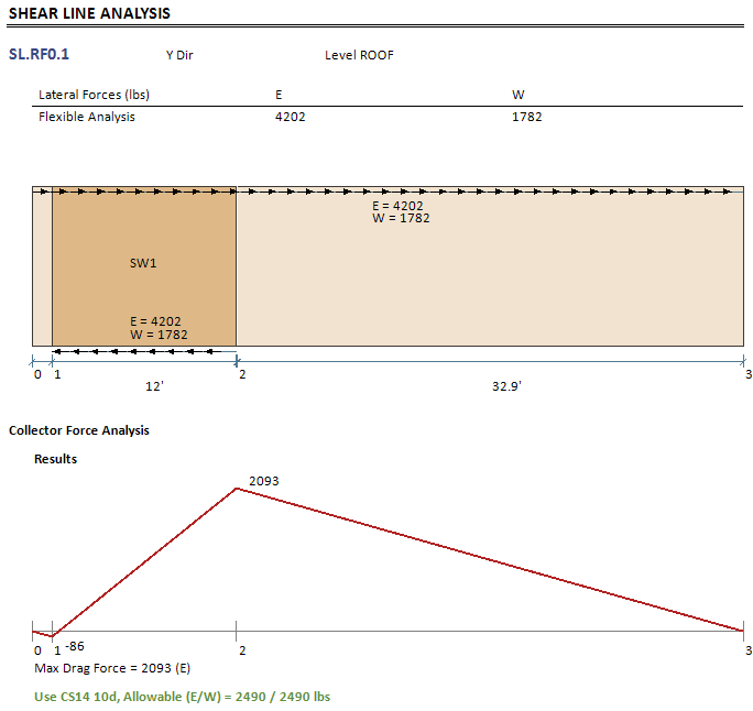
Seismic force for ASD shear wall design is: 0.7 × 4202 = 2941.4 lbs
Use amplification factor Af to convert to seismic force for ASD Collector design: 1 × 2941.4 = 2941.4 lbs
The total collector length is 46.24 ft. The total resisting element (shear wall) length is 12 ft.
ASD diaphragm shear = 2941.4 / 46.24 = 63.6 plf
ASD resisting shear = 2941.4 / 12 = 245.1 plf
Point 0 (0) → Point 1 (1.34 ft), 1.34 ft long
ASD diaphragm shear at Point 1 = 1.34 × 63.6 = 85.2 lbs
ASD resisting shear = 0
ASD Collector force at Point 2 = 85.2 - 0 = 85.2 lbs
Point 1 (1.34 ft) → Point 2 (13.34 ft), 12 ft long
ASD diaphragm shear = 85.2 + 12 × 63.6 = 848.4 lbs
ASD resisting shear = 12 × 245.1 = 2941.2 lbs
ASD Collector force at Point 2 = 848.4 - 2941.2 = -2092.8 lbs
Point 2 (13.34 ft) → Point 3 (46.24 ft), 32.9 ft long
ASD diaphragm shear = -2092.8 + 32.9 × 63.6 = -0.36 lbs
ASD resisting shear = 0
ASD Collector force at Point 2 = -0.36 - 0 = -0.36 lbs ≈ 0
This matches the diagram in LAVA output.
Shear Line 1 on FLOOR1 Level
Shear Line 1 on FLOOR1 Level (SL.FL1.1) is in Y direction, therefore pE for SW is 7.07, pE for Collector is 7.07, and Amplification factor is 7.07 / 7.07 = 1.
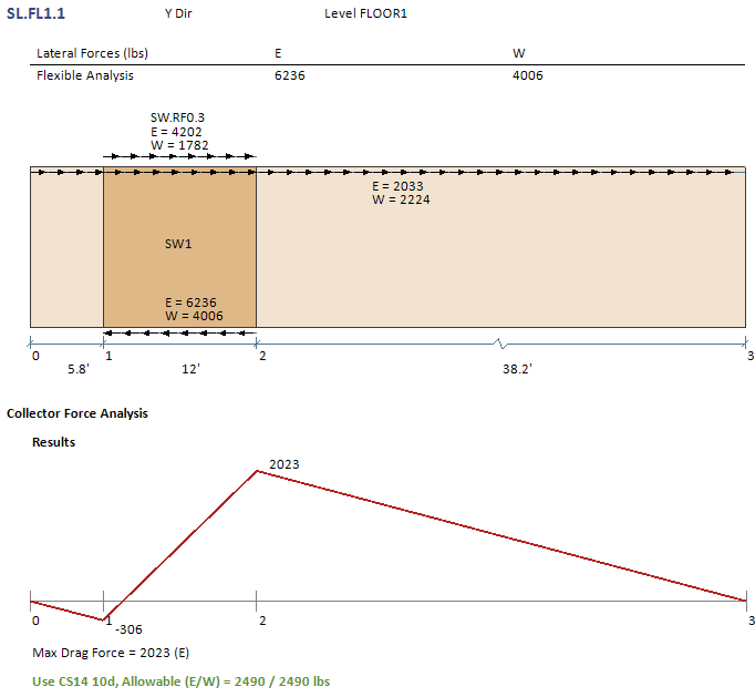
In this demonstration model, there is a shear wall (SW.RF0.3) on top of SL.FL1.1, visit the report page of SW.RF0.3:
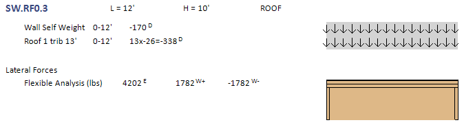
Seismic force of upper level shear wall in ASD is: 0.7 × 4202 = 2941.4 lbs
Seismic force for ASD shear wall design on current level is: 0.7 × 6236 - 2941.4 = 1423.8 lbs
Use amplification factor Af to convert to seismic force for ASD Collector design: 2.08 × 1423.8 = 2961.5 lbs
In this demonstration, SW.RF0.3 is aligned with the SW.FL1.1, which means the upper level shear wall reaction will go to lower level collector directly, therefore the collector force analysis does not need to consider the upper level shear.
So the total seismic force for ASD Collector design is 2961.5 lbs
The total collector length is 55.93 ft. The total resisting element (shear wall) length is 12 ft.
ASD diaphragm shear = 2961.5 / 55.93 = 52.95 plf
ASD resisting shear = 2961.5 / 12 = 246.8 plf
Point 0 (0) → Point 1 (5.77 ft), 5.77 ft long
ASD diaphragm shear at Point 1 = 5.77 × 52.95 = 305.5 lbs
ASD resisting shear = 0
ASD Collector force at Point 2 = 305.5 - 0 = 305.5 lbs
Point 1 (1.34 ft) → Point 2 (13.34 ft), 12 ft long
ASD diaphragm shear = 305.5 + 12 × 52.95 = 940.9 lbs
ASD resisting shear = 12 × 246.8 = 2961.6 lbs
ASD Collector force at Point 2 = 940.9 - 2961.6 = -2020.7 lbs
Point 2 (13.34 ft) → Point 3 (46.24 ft), 38.16 ft long
ASD diaphragm shear = -2020.7 + 38.16 × 52.95 = -0.13 lbs
ASD resisting shear = 0
ASD Collector force at Point 2 = -0.13 - 0 = -0.13 lbs ≈ 0
This matches the diagram in LAVA output.
A Few Notes
Offset Condition
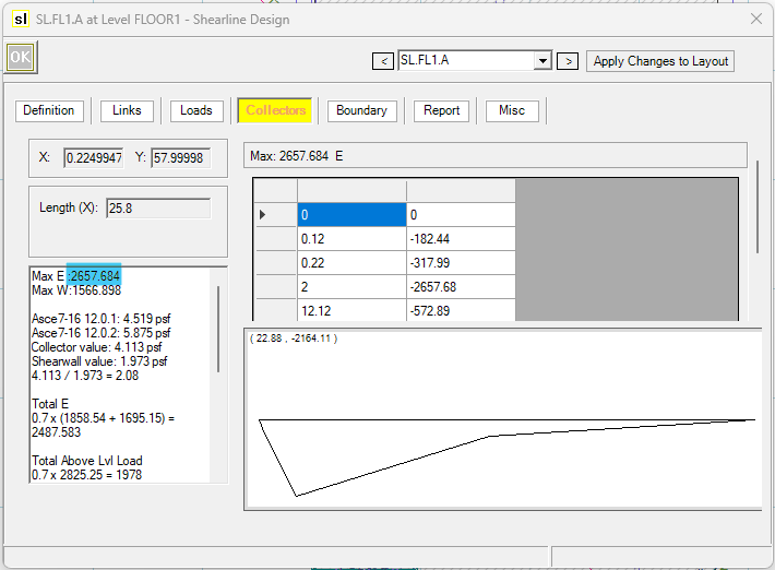
In the demonstration above, SW.RF0.3 is aligned with lower level shear line. What if there is offset between upper level shear wall and lower level shear line? Let’s take a look at Shear Line A on FLOOR1 level.
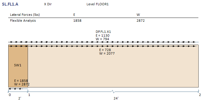
Seismic force of upper level shear wall in ASD is: 0.7 × 1130 = 791 lbs
Seismic force for ASD shear wall design on current level is: 0.7 × 1858 - 791 = 509.6 lbs
Use amplification factor Af to convert to seismic force for ASD Collector design: 2.08 × 509.6 = 1060 lbs
Due to this offset, the upper level shear wall reaction will not go directly to this shear line, and must be included in collector force analysis. So the total seismic force for ASD Collector design is 791 + 1060 = 1851 lbs
Overstrength (Ω) factor
ASCE 7-22 §12.10.2.1 requires collectors and their connections to be designed for seismic load effects including the overstrength factor, Ω₀, where applicable. An exception is provided for qualifying structures or portions of structures braced entirely by wood light-frame shear walls.
By default, LAVA does not apply the Ω₀ factor to the collector forces shown in this article. If the exception does not apply to your project, or if you would like to include Ω₀ factor regardless, please open the Shear Wall Design dialog on the upper level, and go to Definition tab, and check the option ‘Apply over strength factor to drag‘.
Please note: the shear walls on the upper and lower level must not be stacked for Ω₀ factor to apply; if the shear walls are stacked between levels, Ω₀ factor will be ignored in calculation.
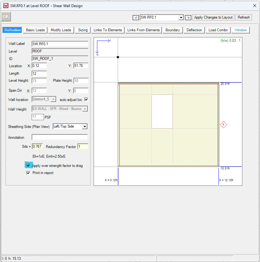
The reaction of this wall will be amplified by Ω₀, and the affected lower level shear line analysis will also see the amplification in seismic force.
Before applying Ω₀:
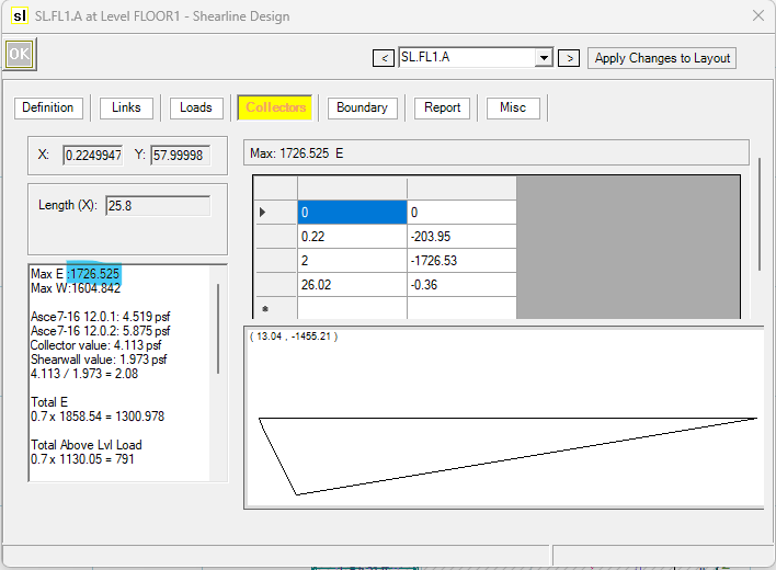
Before applying Ω₀: