In LAVA, lateral analysis (wind and seismic) and vertical analysis (dead load and live load) are addressed separately. But when it comes to bearing wall analysis, component and cladding wind loads must be considered for calculations per NDS Chapter 3.9.2 (Bending and Axial Compression), and deflection calculation as well.
During modeling, Bearing Walls will automatically apply components and cladding wind loads to exterior walls per ASCE 7-16, Chapter 30, Part 1: Low-Rise Buildings. The mean roof height and plate height used in calculation come from Building Definition - Elevations tab.
After the bearing walls are drawn, you can review the design dialog, Definition tab.
.png)
Wall Location - Auto Adjust Location
By default, ‘auto adjust loc‘ is checked, and LAVA will determine the location of the bearing wall automatically basing on the placement of Plates and Bearing Wall elements:
If a Bearing Wall is sandwiched by Plates elements on both sides, this Bearing Wall element will be categized as interior wall.
.png)
If a Bearing Wall has no Plate elements on either side, this Bearing Wall element will be categorized as exterior wall.
.png)
If a longer Bearing Wall has part of body sandwiched by two Plate elements, even though this Bearing Wall element can be considered ‘partial exterior’ and ‘partial interior‘, LAVA will take the more conservative approach and categorize this Bearing Wall as exterior wall. If user doesn’t agree with this approach, they can break this longer shear wall to pieces, so interior and exterior walls can be categorized accordingly.
.png)
Wall Location - Manual Input
User can manually assign the location of a Bearing Wall element. Uncheck ‘auto adjust loc‘, and select the appropriate location. User can also select wall weight accordingly.
.png)
.png)
Exterior4: Calculating Zone 4 wind pressure per Fig.30.3-1
Exterior4_5: Calculating both Zone 4 and Zone 5 wind pressure per Fig.30.3-1, and use the worst-case scenarios for both positive and negative wind pressure
Exterior5: Calculating Zone 5 wind pressure per Fig.30.3-1
Interior: Use 8psf strength level wind pressure
Review Result
User can review the design under ‘Sizing’ tab after a full structural analyze is run.
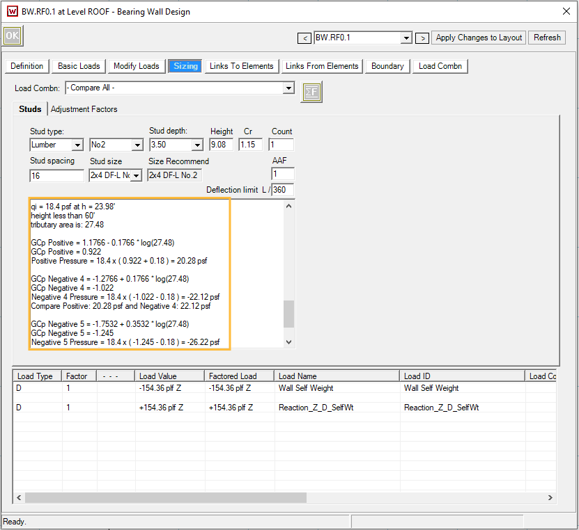
The GCp values are interpolated in Fig.30.3-1 with effective wind area for wall studs.
Below is a quick break-down of the wind pressure calculation of the screenshot above, where wall is categorized as ‘Exterior4_5‘:
.png)