Preferences play a crucial role in optimizing the software program workflow. This allows users to tailor their experience, adjusting settings, layouts, and behavior to meet their specific needs. By providing customization options, preferences enhance user satisfaction and empower individuals to adapt the program to their workflow.
How This Dialog Works
This dialog allows you apply changes to your current project with Apply or OK. If you decide not to make any changes to the current project, click Cancel.
Restore all Preferences to original values: this will take all your preferences back to the factory settings.
Apply current project preferences to new projects: This allows you to save these preferences for all future projects. It will not change existing projects, but it will take effect for all new projects.
Building Definition
.png "image(118).png")
Building Level Default Settings
The building heights are usually typical to a lot of buildings. This setting will help you set these heights in one place for all your jobs. If there are custom specific heights, they can be altered on the Building Definitions- Elevations tab. The Elevations tab will show you the graphical representation of the building in full detail.
Building Layout
.png "image(119).png")
General
Scale/Pan Increment: Value here controls the speed of scroll wheel of mouse in ‘scale’ operation on menu bar.
.png "image(47).png")
Grid Size: Value here controls the size of course grid in ‘Building Layout’ tab. For ‘100’, the course grid is 100 pixels on screen.
Max Undo Count: This undo that is remembered in the program.
Element Size Increment: Value here controls the minimum length increment during modeling structural element, such as beam or shear wall length.
Element Font Size: You can adjust the font size in the graphics to Small, Medium, and Large.
New Element Prompt: User to choose if they want the edit window to pop up after modeling each element. For example, after modeling a beam, the beam edit window will pop up immediately if this box is checked.
Show Action History: User to choose if they want an action history log displayed on the right side of screen in ‘Building Layout’ tab. This will help user track the action that can be undone with Ctrl+Z.
.png "image(48).png")
Element Font Bold: User to choose if they want the texts shown in bold in ‘Building Layout‘ tab.
Shear Line:
Show Name: User to choose if they want shear line name shown in ‘Building Layout‘ tab.
Hide in overlay: User to choose if they want shear line shown in Overlay view in ‘Building Layout‘ tab.
Shear Line Default Settings:
Sizing
These are the options for the Shear Lines.
Conn Type: There are two major types of connections; Wood hold downs or Tie Rods. Based on your selection, you’ll see options for the type of connection that you default for the entire project. Each connection can be defined individually later if you want to vary a specific connection. For Wood connection type, this describes the framing gap to calculate the stiffness of the connection.
Most typically for a 16” Floor to Floor gap with 0.50 Specific Gravity option- this would be selected for Shear Lines with 11-7/8" I-joist floor framing including framing and finish layers.
.png "image(141).png")
.png)
.png)
(Note, Shear Line connectors are not shown in the images above- just shown for reference of framing).
Distribution
This setting allows you to define the distribution based on Capacity or Rigid for lateral loads along the shear line.
.png "image(8).png")
Shear Wall
.png "image(20).png")
Show Name: User to choose if they want shear wall name shown in ‘Building Layout’ tab.
.png "image(49).png")
Hide in overlay: User to choose if they want shear wall shown in Overlay view in ‘Building Layout’ tab.
Show Dimension: User to choose if they want shear wall length shown in ‘Building Layout’ tab.
.png "image(50).png")
Show Shear Wall Size: User to choose if they want shear wall type shown in ‘Building Layout’ tab.
.png "image(51).png")
Show Hold Down Sizes: User to choose if they want hold down shown in ‘Building Layout’ tab.
.png "image(52).png")
Position drop-down menu:
Left/Top Side: Shear wall symbol will be shown on left/top side of shear wall element during modeling after this option is chosen. This will not affect the elements that are previously modeled.
.png "image(17).png")
Right/bottom Side: Shear wall symbol will be shown on right/bottom side of shear wall element during modeling after this option is chosen. This will not affect the elements that are previously modeled.
.png "image(16).png")
Shape drop-down menu:
Diamond: Shear wall symbol will be shown in diamond shape.
.png "image(19).png")
Triangle: Shear wall symbol will be shown in triangle shape.
.png "image(18).png")
Shear Wall Default Setting: User to control default setting for shear walls during modeling. This will not affect shear walls previously modeled
Sizing
.png "image(22).png")
Wall Type: User to choose shear wall construction type: Wood, stud spacing, and wall finish; Simpson Strong Wall; Or Hardy Panel.
Hold Down: User can choose different default settings for Lowest Level (typically foundation level), or Other Levels
.png "image(23).png")
HD Type: User to choose the type of hold down: Wood (Simpson strap or HD), or ATS (tie-down); type and installation (slab on grade, elevated deck, or floor framing).
Hold Down 0 (Left/Top), Hold Down 1 (Right/Bottom): User to choose specific type of installation for each hold down of the same shear wall.
Edge Offset Dist: User to input specific offset distance to calculate compression/uplifting for hold down.
Link
.png "image(24).png")
Lateral Link Margin: User to input specific distance for shear wall lateral reaction to be transferred to. Any structural members located within a range of ‘d’ on either side will be subject to lateral reaction of this shear wall (in-plane shear forces).
Vertical Link Margin: User to input specific distance for shear wall vertical reaction to be transferred to. Any structural members located within a rectangular range of ‘dxd’ on either end will be subject to vertical reaction of this shear wall (hold down compression or uplifting forces).
Bearing Wall
.png "image(25).png")
Show Name: User to choose if they want bearing wall name shown in ‘Building Layout‘ tab.
.png "image(53).png")
Hide in overlay: User to choose if they want bearing wall shown in Overlay view in ‘Building Layout‘ tab.
Show Dimension: User to choose if they want bearing wall length shown in ‘Building Layout‘ tab.
.png "image(54).png")
Show in Report (Bearing Wall): User to choose if they want bearing wall calculation included in final report.
Bearing Wall Default Settings: User to control default setting for bearing walls before modeling. This will not affect bearing walls previously modeled
Sizing
.png "image(26).png")
Stud Type: User to choose the stud species and grade.
Stud Depth: User to choose the stud depth: 3.5” for 2×4 stud wall, or 5.5” for 2×6 stud wall, etc.
Stud Count: User to input the stud count: single, double, or triple studs.
Stud Spacing: User to input the stud spacing
Link
.png "image(27).png")
Vertical Link Margin: User to input specific distance for bearing wall vertical reaction to be transferred to. Any structural members located within a range of ‘d’ on either side will be subject to vertical reaction of this bear wall.
Beam
.png "image(28).png")
Show Name: User to choose if they want beam name shown in ‘Building Layout‘ tab.
.png "image(55).png")
Hide in overlay: User to choose if they want beam shown in Overlay view in ‘Building Layout‘ tab.
Show Dimension: User to choose if they want beam length shown in ‘Building Layout‘ tab.
.png "image(56).png")
Show Member Size: User to choose if they want beam size shown in ‘Building Layout‘ tab.
.png "image(57).png")
Inches added using snap function: User to input the offset distance of snap function when modeling beams. For 1.75”, LAVA will automatically add 1.75” length on each end of beam to count in bearing length.
Beam Default Setting: User to control default setting for beam before modeling. This will not affect beams previously modeled.
Sizing
.png "image(29).png")
Type: User to choose beam species (DFL, LSL, PSL, GLB, W Beam, etc.) and grade if applicable.
Width: User to limit the selection pool to specific width.
Depth: User to limit the selection pool to specific depth.
Multi Beam: User to input beam count for each beam modeled. Input ‘2’ if user wishes to model sister-ed double beam.
Link
.png "image(30).png")
Vertical Link Margin: User to input specific distance for beam vertical reaction to be transferred to. Any structural members located within a rectangular range of ‘dxd’ on either end will be subject to vertical reaction of this beam.
Plate
.png "image(31).png")
Show Name: User to choose if they want plate name shown in ‘Building Layout‘ tab.
.png "image(58).png")
Hide in overlay: User to choose if they want plate shown in Overlay view in ‘Building Layout‘ tab.
Show Dimension: User to choose if they want plate dimension shown in ‘Building Layout‘ tab.
.png "image(59).png")
Plate Default Setting: User to control default setting for plate before modeling. This will not affect plates previously modeled.
Link
.png "image(32).png")
Vertical Link Margin: User to input specific distance for plate loads to be transferred to. Any structural members located within a range of ‘d’ on either side of supported edge of plate will be subject to vertical force of this plate.
Diaphragm
.png "image(33).png")
Show Name: User to choose if they want diaphragm name shown in ‘Building Layout‘ tab.
.png "image(60).png")
Hide in overlay: User to choose if they want diaphragm shown in Overlay view in ‘Building Layout‘ tab.
Show Dimension: User to choose if they want diaphragm dimension shown in ‘Building Layout‘ tab.
.png "image(61).png")
Show link margins when selected: User to choose if they want link margin shown when diaphragm is selected in ‘Building Layout‘ tab. Link margins are shown with orange dash lines.
.png "image(34).png")
Diaphragm Default Setting: User to control default setting for diaphragm before modeling. This will not affect diaphragms previously modeled
Link
.png "image(36).png")
Lateral Link Margin: User to input specific distance for diaphragm loads to be transferred to. Any structural members located within a range of ‘d’ on either side of supported edge of diaphragm will be subject to lateral force of this diaphragm.
Post: User can choose different default settings for Lowest Level (typically foundation level), or Other Levels before modeling. This will not affect posts previously modeled
.png "image(37).png")
Post Type: User to choose post species and grade.
Post Depth: User to limit the selection pool to specific depth.
Multi Post: User to choose post count for each post modeled. Select ‘2‘ if user wishes to model a post consists of double studs.
Use Overstrength Factor for Sole/Sill Plate Bearing: User to choose if they want to include overstrength factor when checking sill plate bearing.
Check Wood Panel Bearing: User to choose if they want to check the bearing capacity of floor sheathing.
Use Overstrength Factor for Wood Panel Bearing: User to choose if they want to include overstrength factor when checking floor sheathing bearing.
Sole Plate Thickness (applicable at Other Levels): User to input sole plate thickness. Input 3 if double sill plates are present.
DXF
.png "image(38).png")
Show Name: User to choose if they want background DXF name shown in ‘Building Layout‘ tab.
Hide in overlay: User to choose if they want background DXF shown in Overlay view in ‘Building Layout‘ tab.
Design Procedure
.png "image(40).png")
Reduction in Roof Live Loads (base on slope): User to choose if they want LAVA to automatically reduce roof live load if roof slope is over 4:12.
Seismic
.png "image(41).png")
Use highest level height for hn (both X and Y directions): User to choose if they want to use the highest hn value when calculating fundamental period.
Wind
.png "image(42).png")
Add eccentricity at center of wind: User to choose if they want to calculate torsion caused by eccentricity in wind loads.
Method
.png "image(43).png")
Number of iterations for shear line: User to input the maximum iterations for shear line to make all shear panels have identical deflection in the same shear line.
Rigid:
Number of iterations for rigid analysis: During the rigid analysis, the distribution of forces is recalculated as elements are re-designed. This number sets the number of iterations before the design is stopped.
Enable Ecc Ld for Seismic/Wind: These are the settings for Accidental Torsion per ASCE 7-22 Section 12.8.4.3.
Center of Mass/Wind Offset: The code prescribes 5% application of load to accomplish the torsional irregularity load application. You can turn this option off by setting this to 0%.
Reset
Schedules and settings get “Locked” in order to ???
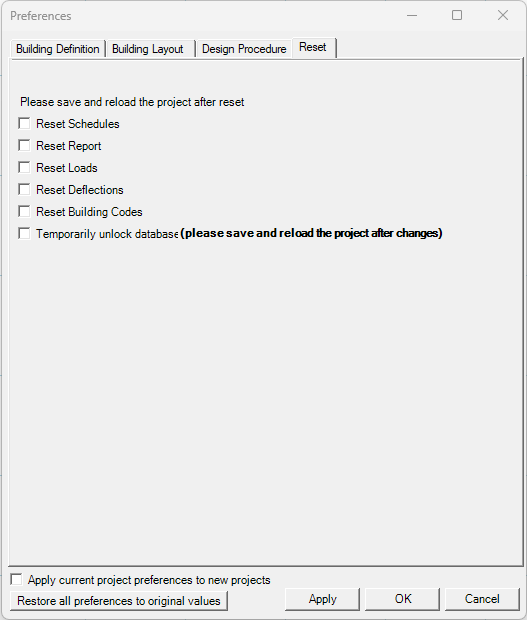
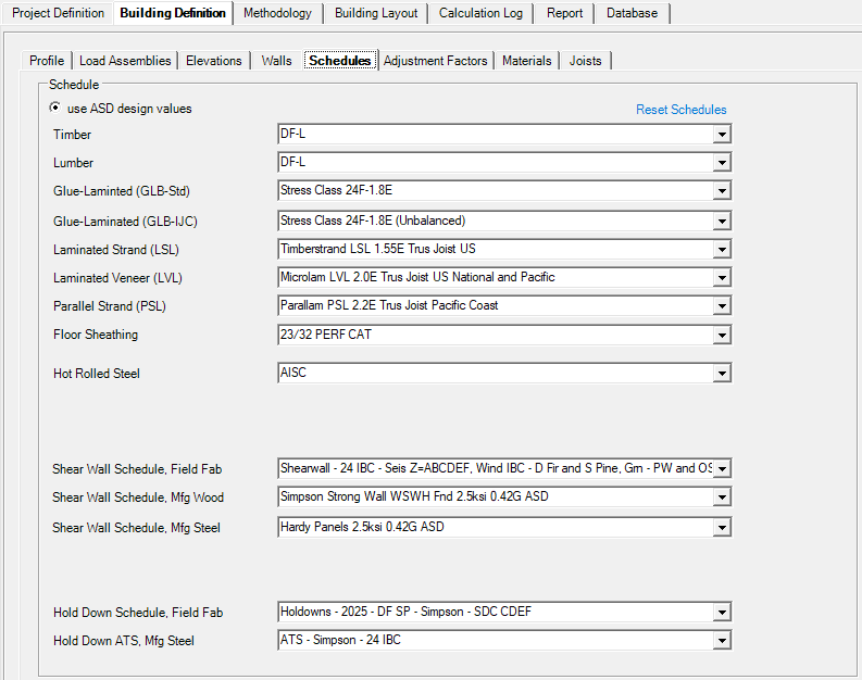
Reset Schedules: User can reset all schedules under ‘Building Definition’, ‘Schedule’.
Reset Building Codes: This allows the user to change the building code after the model has been saved/re-opened.
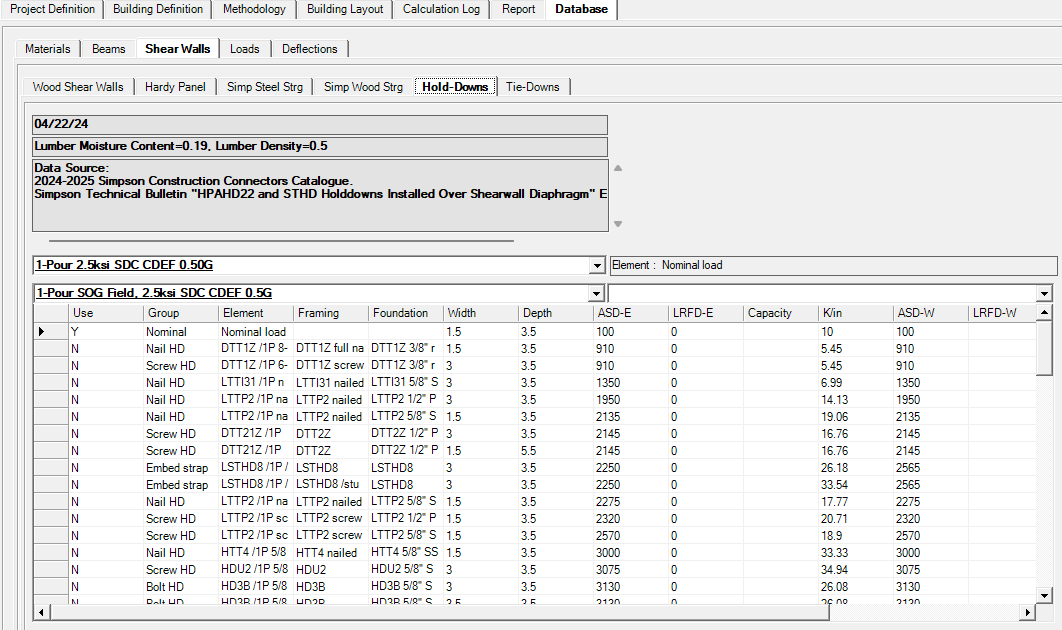
Temporarily unlock database: User can temporarily make changes to database under ‘Database’ to add or remove items such as beam species, hold down hardware, etc.