The software is fully automated to transfer the gravity loads down the building. This article helps describe the hierarchy of the load transfer.
As loads are applied to the floor plan, they are first transferred on that same floor to the elements. Then the load is transferred to the floor below to the elements on that level. This article will break up the hierarchy in those two ways.
Gravity Load Transfer
Same Level Load Transfer
Roof/Floor Framing (Plate)—>
Beam/Post
Bearing Wall
Shear Wall
Beam/Post —>
Beam/Post
Shear Wall
Floor Below Load Transfer
Bearing Wall Above —>
Beam/Post
Bearing Wall
Floor Framing (Plate)
Shear Wall
Roof/Floor Framing (Plate) Above —>
Bearing Wall
Floor Framing (Plate)
Shear Wall
Beam/Post Above —>
Beam/Post
Shear Wall
Shear Wall Above —>
Beam/Post
Shear Wall
Prioritizing When Multiple Members Meet at Same Location
Scenario: three beams (BM.FL1.1a, BM.FL1.2, and BM.FL1.3) meet exactly at one point of location at floor level, and the point aligns with the right end of a shear wall (SW.RF0.1) at roof level.
Each member is assigned an internal ID in LAVA. By default, the Beam Name is consistent with the internal ID, and the sequence of modeling. For example, the first beam modeled on FLOOR1 level by user will be named ‘BM.FL1.1’, with internal ID as ‘BM_FLOOR1_1’, and the second beam will be named ‘BM.FL1.2’, with internal ID as ‘BM_FLOOR1_2’, etc. User can edit the Beam Name, but the internal ID will remain the same.
When a load is within the link margins of multiple members like the beams in the screenshot below, LAVA will prioritize basing on the sequence of internal ID, not Beam Name. In this example, the load from right end of shear wall on ROOF level will go to BM.FL1.3, because the internal ID of BM.FL1.3 is ‘BM_FLOOR1_1’, on top of the list of all three beams.
You can verify this by opening Beam Design dialog, and going to ‘Links to Elements’ tab, where the load path is listed.

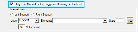
If you would like to assign the load to a specific beam, please use the manual link option under ‘Links to Elements’ tab.
Lateral Load Transfer
Same Level Load Transfer
Diaphragm —> Shear Line —> Shear Wall
Note: Shear Line is required to transfer loads from Diaphragm to Shear Walls. The forces will not go directly from the diaphragm to the shear wall without a shear line.
Floor Below Load Transfer
Shear Wall —>
Shear Line
Shear Wall
Diaphragm