At this time, the analysis of diagonal walls and beams are not supported in LAVA. However, you can idealize the building in ways that gets you the results you’re looking for. This article shows one method to building a model to analyze a structure with non-orthogonal walls.
Method 1 Modeling Diagonal Shear Walls in LAVA Using Orthogonal Components
Diagonal shear walls show up all the time in real buildings. Think angled garages, rotated cores, or site-driven geometry where nothing lines up perfectly with your global X–Y grid.
LAVA models lateral systems in orthogonal directions. So when you have a 45-degree wall (or any skewed wall), the cleanest way to handle it is to resolve that wall into its orthogonal components.
Concept: Resolve the 45° Wall into X and Y Vectors
Instead of trying to model a single 45° shear wall element, break it into two components:
One wall in the X direction
One wall in the Y direction
You are essentially treating the diagonal wall as a vector and resolving it into orthogonal components.
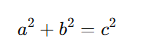
For a 45° wall, the geometry works in your favor because:
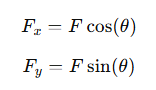
More generally:
For θ = 45°:
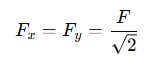
This makes the method especially accurate at 45°, since both components are equal and align cleanly with LAVA’s orthogonal force-resisting system.
Step-by-Step Workflow in LAVA
Step 1 – Draw Two Orthogonal Walls
Instead of drawing a single diagonal wall:
Draw one shear wall aligned with X
Draw one shear wall aligned with Y
Place them at the same physical location as the intended 45° wall
Each wall represents one vector component of the diagonal system.
Step 2 – Break the Wall into Directional Vectors
You are not duplicating capacity arbitrarily. You are distributing force components.
If the diagonal wall would resist total force F, assign:
X wall → Fx
Y wall → Fy
At 45°:
Fx = Fy
For other angles:
Use cosine/sine resolution.
Step 3 – Match Diaphragms to X and Y Directions
Since LAVA distributes lateral forces along orthogonal axes:
Ensure diaphragms are defined in X and Y directions
Connect each shear wall to its appropriate shear line
Confirm load paths are consistent in both axes
If needed, slightly oversize the diaphragm to account for the geometric approximation. This is often reasonable when the diaphragm is relatively stiff compared to the wall system.
Why This Method Works
Structurally, lateral resistance is vector-based.
When a diagonal wall resists force F at angle θ, the structure does not “feel” that as a single directional action. It feels:
An X component
A Y component
By modeling two orthogonal walls, you are explicitly capturing those resolved force components within LAVA’s solver.
For 45° walls, this method is particularly clean because:
Equal force components
Symmetric stiffness behavior
Wind & Seismic loads are generally discussed in orthogonal directions
Interpreting the Results
After design is complete, LAVA will show:
Capacity for the X wall
Capacity for the Y wall
To determine the equivalent diagonal capacity, resolve back to the resultant force:
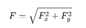
This is simply:
If both components are equal (45° case):
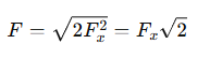
This gives you the equivalent force that the original diagonal wall can resist.
Engineering Considerations
A few important points to keep in mind:
1. Stiffness Effects
You are approximating the diagonal wall as two orthogonal systems. For most practical wood-framed buildings, this is acceptable, particularly at 45°.
2. Diaphragm Interaction
Since diaphragm forces distribute orthogonally in LAVA, you will need to check outside of LAVA the diaphragm interaction.
3. Documentation
When submitting for plan check, document:
The vector resolution approach
The reconstruction of diagonal force using √(Fx² + Fy²)
This keeps the logic transparent.
4. When to Use This Method
This approach works best when:
The wall is 45°
The building is primarily orthogonal
The diagonal wall is isolated, not part of a rotated full building system
If the entire structure is rotated, consider aligning the global grid instead of using vector resolution.
Method 2 Rotating the Model to Approximate the Diagonal Walls
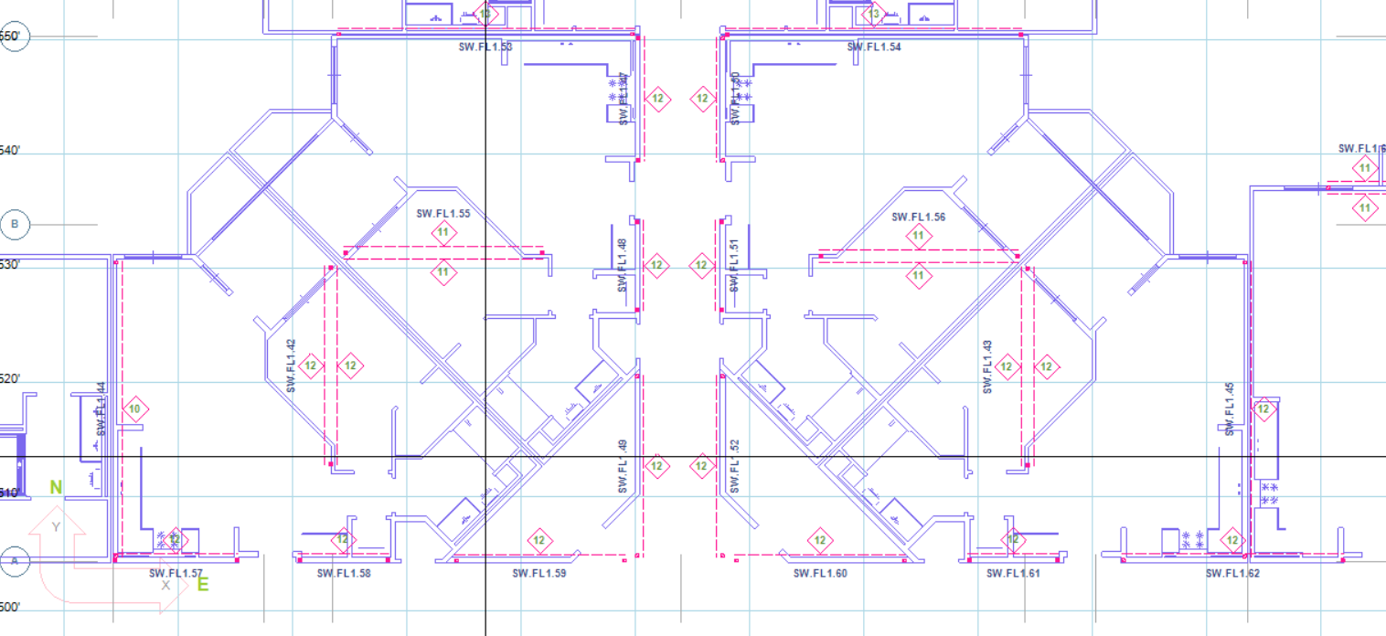
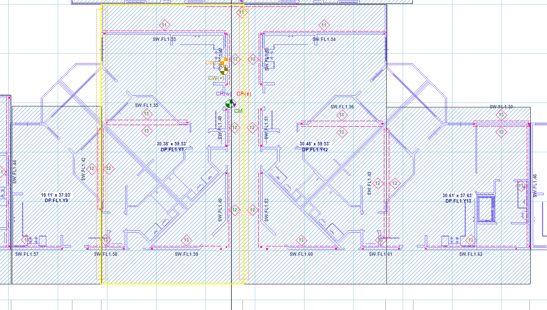
Please see the screenshot below for a section of a building as an example, with a layout of walls in various angles. Beam 1 and Beam 2 are placed with angles, and are subject to trapezoidal area loads. Beam 3 is placed in y axis, but is also carrying reaction of Beam 2.
.png "image(412).png")
Adjust DXF Background
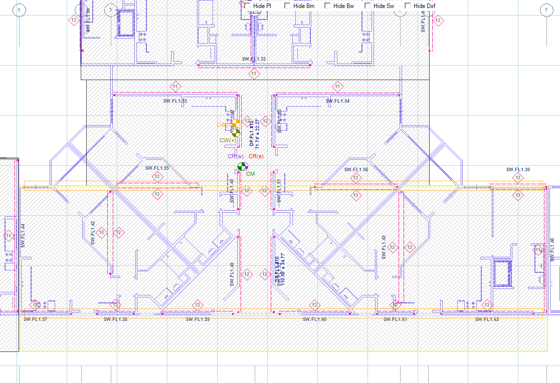
The structural elements in LAVA (plates, diaphragms, beams, shear walls, bearing walls) can only be placed in orthogonal axes. The first step is to ‘straighten’ the layouts in background. The background in LAVA is imported DXF files, which can be easily edited by any CAD program. Please see the screenshot below for one way to modify the background:
.png "image(409).png")
Applying Trapezoidal Load
LAVA does not support trapezoidal area load currently. You can either model one larger plate to apply load conservatively (Plate 1), or model a few smaller strips of plates to simulate a trapezoidal plate (Plate 2 to 9).
.png "image(416).png")
Apply Beam Reaction with Manual Link
.png "image(415).png")
Model Beam 1, 2, 3 and Header 1 in the model space. LAVA will automatically apply loads to them via plates. Since the left end of Beam 2 does not sit on Beam 3 in the model space, LAVA will not apply left reaction of Beam 2 to Beam 3 automatically. You must link this reaction manually.
Open Beam Design dialog of Beam 2, and go to ‘Links To Elements’ tab:
.png "image(418).png")
Notice that currently there is no items listed in the summary. This is consistent with the model space.
In ‘Manual Link’ section, select Left support, and select Beam 3 from the drop-down menu, input the correct ‘Start’ location, and press .png "image(420).png") :
:
.png "image(419).png")
This operation will manually add left reaction of Beam 2 to Beam 3 at 1.25’ measured from left end of Beam 3. The ‘Links To Element’ tab will be updated:
.png "image(417).png")
Click .png "image(421).png") to save the revision and close the dialog. Run a full scale analyze by pressing Analyze
to save the revision and close the dialog. Run a full scale analyze by pressing Analyze .png "image(422).png") on toolbar. Open Beam Design dialog of Beam 3, and go to ‘Links From Elements’:
on toolbar. Open Beam Design dialog of Beam 3, and go to ‘Links From Elements’:
.png "image(423).png")
It is shown that the manual link from Beam 2 is considered in calculation of Beam 3.