Profile
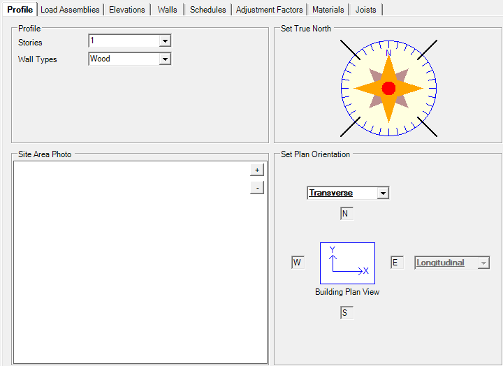
Stories: User can design structures up to 6 levels.
Wall Types: User to assign wall type.
Site Area Photo: User can upload site area photo. This will be part of calculation report at Wind Load section.
Set Plan Orientation: By default, LAVA assume ridge along longitudinal direction. User can override in individual diaphragm settings.
This setting is used to calculate the wind loads.
Load Assemblies
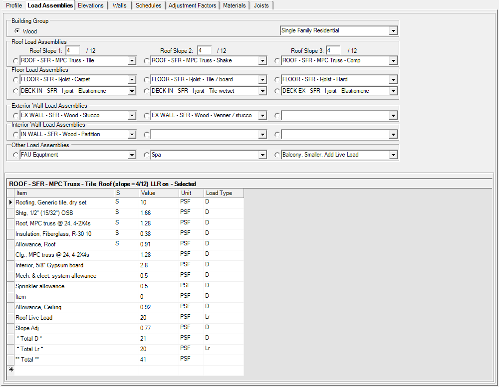
Building Group: User to choose light frame material, and access to an extensive database of pre-defined load assemblies.
Roof Load Assemblies: User can define up to 3 different roof load assemblies with different roof slope. By checking the dot mark on the left of drop-down menus, user selects the one assembly that user wishes to use as default load assembly during modeling in ‘Building Layout’ tab. The dead load in default load assembly will also be used to calculate seismic weight.
.png "image(64).png")
Floor Load Assemblies: User can define up to 6 different floor load assemblies with different live loads. By checking the dot mark on the left of drop-down menus, user selects the one assembly that user wishes to use as default load assembly during modeling in ‘Building Layout’ tab. The dead load in default load assembly will also be used to calculate seismic weight.
.png "image(68).png")
Exterior Wall Load Assemblies: User can define up to 3 different exterior wall load assemblies with different finishes. By checking the dot mark on the left of drop-down menus, user selects the one assembly that user wishes to use as default load assembly during modeling in ‘Building Layout’ tab. The dead load in default load assembly will also be used to calculate seismic weight.
.png "image(69).png")
Interior Wall Load Assemblies: User can define up to 3 different interior wall load assemblies with different finishes. By checking the dot mark on the left of drop-down menus, user selects the one assembly that user wishes to use as default load assembly during modeling in ‘Building Layout’ tab. The dead load in default load assembly will also be used to calculate seismic weight.
.png "image(70).png")
Other Load Assemblies: User can define up to 3 different special load assemblies if needed. By checking the dot mark on the left of drop-down menus, user selects the one assembly that user wishes to use as default load assembly during modeling in ‘Building Layout’ tab. The dead load in default load assembly will also be used to calculate seismic weight.
.png "image(71).png")
By selecting any pre-defined load assembly, user can modify the itemized content as needed. User must press ‘Apply Changes’ after modifications to register the change.
.png "image(74).png")
Item: User can modify the name for each item.
S: User to choose if they want this item to increase per slope. This is only applicable to roof load assemblies. At this time, this field should not be adjusted.
Value: User can modify the load amount for each item.
Unit: This is editable but should be left as PSF as these are area loads.
Load Type: User to choose the load type for each item when applicable (Dead load D, or Live load L or Live load roof Lr).
Elevations
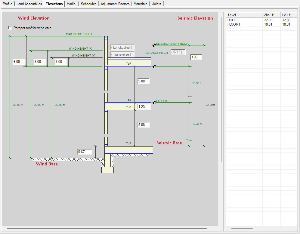
The levels shown in the diagram is determined by the value in ‘Stories’ under ‘Profile’ tab.
The roof type shown in the diagram is determined by the roof slope of default roof load assembly under ‘Load Assemblies’ tab. If roof slope no more than 1.2 / 12, the diagram will show flat roof with parapet (shown above); if roof slope is over 1.2 / 12, the diagram will show pitched roof:
.png "image(76).png")
Parapet roof for wind load calc.: User to choose if they wish to include parapet wind force per ASCE 7 Chapter 27.4.5.
.png "image(138).png")
MAX. BLDG HEIGHT: This value is not used in calculation. This number is for information purpose only, and can be compared to the values of WIND HEIGHT (X) and WIND HEIGHT (Y) for reference.
WIND HEIGHT (X) and WIND HEIGHT (Y): These two values, Wx and Wy, are mean roof heights in X and Y direction. The calculation will use the average of the two to calculate Mean Roof Height for the entire project: (Wx + Wy) / 2.
For flat roof: Wx or Wy is used to calculate height above top plates. For example, for 10.08 plate height, and 3.00 Wx value, the wind force at roof level = wind pressure x (10.08 / 2 + 3.00), which is the summation of half of plate height and Wx value.
For gable roof: in Longitudinal direction, the wind pressure is on wall, and wind force is calculated in the same way as flat roof above; in Transverse direction, the wind pressure is on slope roof and calculated basing on roof slope and diaphragm depth per ASCE 7-16 Fig. 27.3-1.
SEISMIC HEIGHT ROOF: This value is the height of center of mass above top plates. This number is used to calculate the vertical distribution of seismic force per ASCE 7-16 Section 12.8.3.
This image helps demonstrate how the elevations are shown with framing.
.png)
Walls
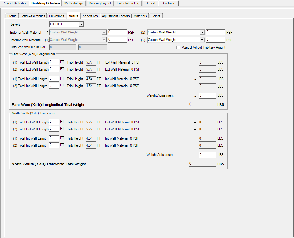
Levels: All levels shown in ‘Elevation’ tab are listed in the drop-down menu. User must input wall length for each level to calculate appropriate seismic weight.
Exterior Wall Material (1): Here displays the default exterior wall dead load that user previously defined in ‘Load Assemblies’ tab.
Exterior Wall Material (2): User can add additional type of exterior wall material to accurately calculate seismic weight when applicable.
Interior Wall Material (1): Here displays the default interior wall dead load that user previously defined in ‘Load Assemblies’ tab.
Interior Wall Material (2): User can add additional type of interior wall material to accurately calculate seismic weight when applicable.
Total est. wall len in DXF: LAVA will measure the length of lines from the DXF background that user imported under ‘Building Layout’ tab, and lists an estimated wall lengths in X and Y directions. This is for user’s reference only, not to be used without user’s own judgement.
Manual Adjust Tributary Height: LAVA will use half of level height that user defined under ‘Elevation’ tab as tributary heights when calculating seismic weight. If user wishes to override this value, they can check this option and input ‘Trib Height’ manually.
East-West (X dir) Longitudinal
.png "image(79).png")
(1) Total Ext Wall Length: User to input total length of exterior walls with default load assembly in X direction.
.png")
Trib Height: If user checks the option ‘Manual Adjust Tributary Height’ above, the cell will be editable, and user will be able to input custom tributary height for this level.
Parapet Height: Default tributary height for each level is half of level height. If parapet is present at roof level, user must input parapet height so parapet weight is also included in seismic weight.
(2) Total Ext Wall Length: If user defines additional wall weight assembly for exterior wall, they can input the wall length accordingly.
(1) Total Int Wall Length: User to input total length of interior walls with default load assembly in X direction.
.png")
(2) Total Int Wall Length: If user defines additional wall weight assembly for interior wall, they can input the wall length accordingly.
Weight Adjustment: LAVA will calculate the summation of wall weight that user has input. User can make adjustments if applicable.
North-South (Y dir) Transverse
.png "image(82).png")
(1) Total Ext Wall Length: User to input total length of exterior walls with default load assembly in Y direction.
.png")
Trib Height: If user checks the option ‘Manual Adjust Tributary Height’ above, the cell will be editable, and user will be able to input custom tributary height for this level.
Parapet Height: Default tributary height for each level is half of level height. If parapet is present at roof level, user must input parapet height so parapet weight is also included in seismic weight.
(2) Total Ext Wall Length: If user defines additional wall weight assembly for exterior wall, they can input the wall length accordingly.
(1) Total Int Wall Length: User to input total length of interior walls with default load assembly in Y direction.
.png")
(2) Total Int Wall Length: If user defines additional wall weight assembly for interior wall, they can input the wall length accordingly.
Weight Adjustment: LAVA will calculate the summation of wall weight that user has input. User can make adjustments if applicable.
Schedule
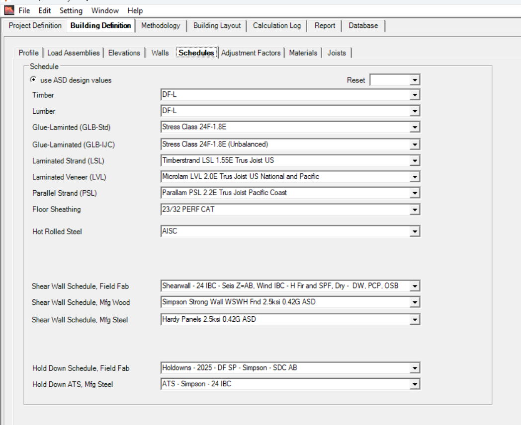
Timber: User to choose wood species for members that are 6x or larger.
Lumber: User to choose wood species for members that are 2x or 4x.
Glue-Laminated (GLB-Std): User to choose species and grade for standard glulam members.
Glue-Laminated (GLB-IJC): User to choose species and grade for I-Joist compatible glulam members.
Laminated Strand (LSL): User to choose LSL manufacturers.
Laminated Veneer (LVL): User to choose LVL manufacturers.
Parallel Strand (PSL): User to choose PSL manufacturers.
Floor Sheathing: User to choose floor sheathing thickness.
Hot Rolled Steel: User to choose specification standard for hot rolled steel members.
Shear Wall Schedule, Field Fab: User to choose field-fabricated plywood shear wall schedule that is appropriate for stud species and seismic design categories for user’s project.
Shear Wall Schedule, Mfg Wood: User to choose pre-manufacturer wood shear wall manufacturers.
Shear Wall Schedule, Mfg Steel: User to choose pre-manufacturer steel shear wall manufacturers.
Hold Down Schedule, Field Fab: User to choose holddown manufacturer that is appropriate for stud species and seismic design categories for user’s project.
Hold Down ATS, Mfg Steel: User to choose tie-down system manufacturer.
Reset - The database gets locked once the model is saved and closed. This button allows you to Reset the schedules if you need to make changes. You can also reset the schedules from the Preferences.
All - this will reset all the databases (Beams, Hold Downs, Shear walls, and ATS)
All exclude SW- this will reset all the databases listed above except it will preserve your Shear wall schedule. This is helpful to keep your customized SW schedule.
Beams- this will only reset the beam schedules (Timber/Lumber and all manufactured wood, AISC).
HD- this will only reset the Hold Down- Field Fab schedule.
ATS- this will only reset the ATS, Mfg Steel schedule
Adjustment Factor
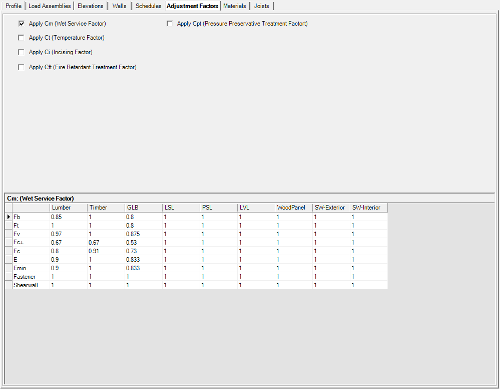
User to check appropriate adjustment factors to be used in this project.
Cm: Wet service factor
Ct: Temperature factor
Ci: Incising factor
Cft: Fire retardant treatment factor
Cpt: Pressure preservative treatment factor
Please note that: if checked, the parameters will be applied to all structural members that are applicable. User can make adjustments in individual member design dialog.
Materials
This is optional data and does not affect the calculations. User can edit this text field to match construction documents. This page can be part of calculation report if user chooses to include it.
Joists
This is optional data and does not affect the calculations. User can edit this text field to match construction documents. This page can be part of calculation report if user chooses to include it.